Z carburetor adjustment, Pump, Tire pressure – MTD 242-610-000 User Manual
Page 9: Installation of tire to rim, Off-season storage
Attention! The text in this document has been recognized automatically. To view the original document, you can use the "Original mode".
FLEXIBLE PUMP COUPLER
JTS
a
/
ctt
a
------------ ¡Z--------------- CARBURETOR ADJUSTMENT
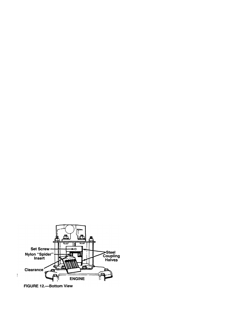
The flexible pump coupler is a nylon “spider” insert,
located between the pump and engine shaft. The
alignment is very critical. Over a period of time, the
coupler will harden and deteriorate. For a replace
ment flexible pump coupler, order part number 717-
0891.
A
WARNING: Never hit the pump shaft in
any manner, as any blow will cause per
manent damage to the pump.
When replacing the flexible pump coupling, proceed
as follows.
1. Place the coupling half onto the engine shaft.
Make certain there is clearance between the cou
pling half and the engine. Tighten the set screw.
2. Mount the pump onto the coupling support brack
et. Tighten securely.
3. Carefully slide coupling half onto pump shaft
(make certain set screw is loose). Slide the key
into place on the shaft.
4. Install the nylon “spider” insert into coupling half
on the engine shaft.
5. Place the coupling shield in position on the hex
bolts. Rotate the keyway on the pump shaft so it
is toward the bottom.
6. Attach the coupling support bracket to the hex
bolts, carefully sliding the coupling half over the
“spider” insert. Secure coupling shield and cou
pling support bracket with lock washers and hex
nuts. Tighten securely.
7. Adjust the two coupling halves (steel) so there is
between .010“ and .060" clearance between the
two halves (at least the thickness of a matchbook
cover, up to 1/16" maximum). See figure 12.
Tighten the set screw in the coupling half on the
pump shaft.
NOTE: Make certain proper clearance is obtained
before tightening set screw.
PUMP
A
WARNING: If any adjustments are made
to the engine while the engine is running
(e.g. carburetor), keep clear of all moving
parts. Be carefui of heated surfaces and
muffler.
Minor carburetor adjustment may be required to com
pensate for differences in fuel, temperature, altitude
or load. Improper adjustment will cause stalling when
splitting is under load, hard starting and higher fuel
consumption.
Refer to the separate engine manual packed with
your log splitter for carburetor adjustment information.
NOTE: A DIRTY AIR CLEANER WILL CAUSE
ENGINE TO RUN ROUGH. BE CERTAIN AIR
CLEANER IS CLEAN AND ATTACHED TO THE
CARBURETOR BEFORE ADJUSTING CARBURE
TOR. DO NOT MAKE UNNECESSARY ADJUST
MENTS. FACTORY SETTINGS ARE SATISFACTO
RY FOR MOST APPLICATIONS AND CONDITIONS.
TIRE PRESSURE
Check sidewall of tire for manufacturer’s recommend
ed maximum tire pressure. If this information does not
appear on your tire, maximum tire pressure under any
circumstances is 30 p.s.i. Equal pressure should be
maintained on both tires.
INSTALLATION OF TIRE TO RIM
A
1
.
2
.
3.
WARNING: The following procedure must
be followed when removing or installing
a tire to the rim.
Be certain rim is clean and free of rust.
Lubricate both the tire and rim generously.
Never inflate to over 30 p.s.i. to seat beads.
Excessive pressure when seating beads may
cause tire/rim assembly to burst with force suffi
cient to cause serious injury.
OFF-SEASON STORAGE
If the log splitter will not be used for a period longer
than 30 days, the following steps should be taken to
prepare the log splitter for storage.
1. Clean the engine and the entire log splitter
thoroughly.
2. Refer to the engine manual for correct engine stor
age instructions. Follow instructions carefuily.
3. Wipe unit with an oiled rag to prevent rust, espe
cially wedge and beam.
4. Store unit in a clean, dry area. Do not store next
to corrosive materials, such as fertilizer.
NOTE: When storing any type of power equipment in
an unventilated or metal storage shed, care should be
taken to rustproof the equipment by coating with a
light oil or silicone.