Attaching the control handle, Final assembly, Operation – MTD 242-610-000 User Manual
Page 6: Initial preparation, Service engine with gasoline anc oil as
Attention! The text in this document has been recognized automatically. To view the original document, you can use the "Original mode".
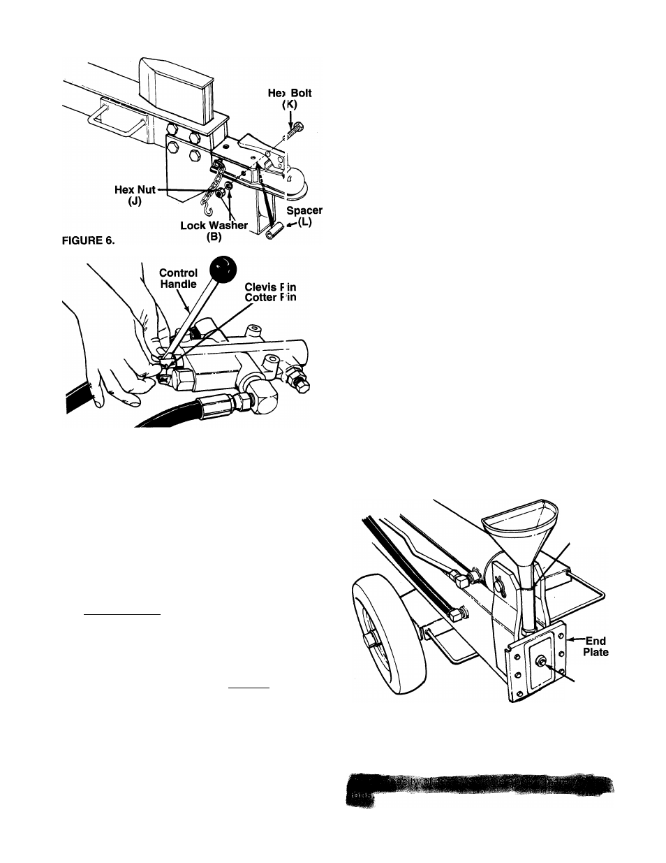
2. Place spacer (L) inside the beam stand. Insert
hex bolt (K) through forward hole in hitch, beam
— stand and spacer. Secure with lock washer (B)
and hex nut (J). See figure 6.
3. Tighten both bolts and nuts securely using two
9/16" wrenches.
ATTACHING THE CONTROL HANDLE
1. The bottom of the control handle is already
attached to the valve with a cotter pin. Remove
the second cotter pin and clevis pin which are
attached to the valve only.
2. Place the handle in position, and secure using
the clevis pin and cotter pin. Secure by bending
the ends of the cotter pin in opposite directions.
See figure 7.
FIGURE 7.
FINAL ASSEMBLY
1. Make certain all nuts, bolts and hose clamps are
tightened securely.
2. Before operating the log splitter, make certain to
follow the “Initial Preparation” instructions in the
Operation Section.
OPERATION
INITIAL PREPARATION
1. Place the log splitter on a firm, level surface.
2. Service engine with gasoline anc oil as
instructed in the separate engine manua packed
with your log splitter.
3. Lubricate the area of the beam on which the ram
will slide with automotive grease.
4. Fill the reservoir tank (beam) and purgo the air
from the system as follows.
------ - “
a. With the log splitter on a level surface remove
the cap from the breather tube. See figure 8.
Remove the fluid check plug from the end
plate.
b. Fill the reservoir tank with Dexron II automatic
transmission fluid until fluid starts to c ome out
of the hole. Replace the check plug.
c. Start the engine. Slowly move the cortrol han
dle forward and backward until the rai n moves
smoothly in both directions.
d. Stop the engine. Remove the fluid ch^ick plug.
Add fluid as necessary until fluid »tarts to
come out of the hole. Replace the check plug.
Breather
Tube
Fluid
Check
Plug
FIGURE 8.
e. Repeat steps “c” and “d” until the ram oper
ates smoothly and the fluid level is correct.
Then replace the breather cap securely.