Note – MTD 94-2105-B User Manual
Page 7
Attention! The text in this document has been recognized automatically. To view the original document, you can use the "Original mode".
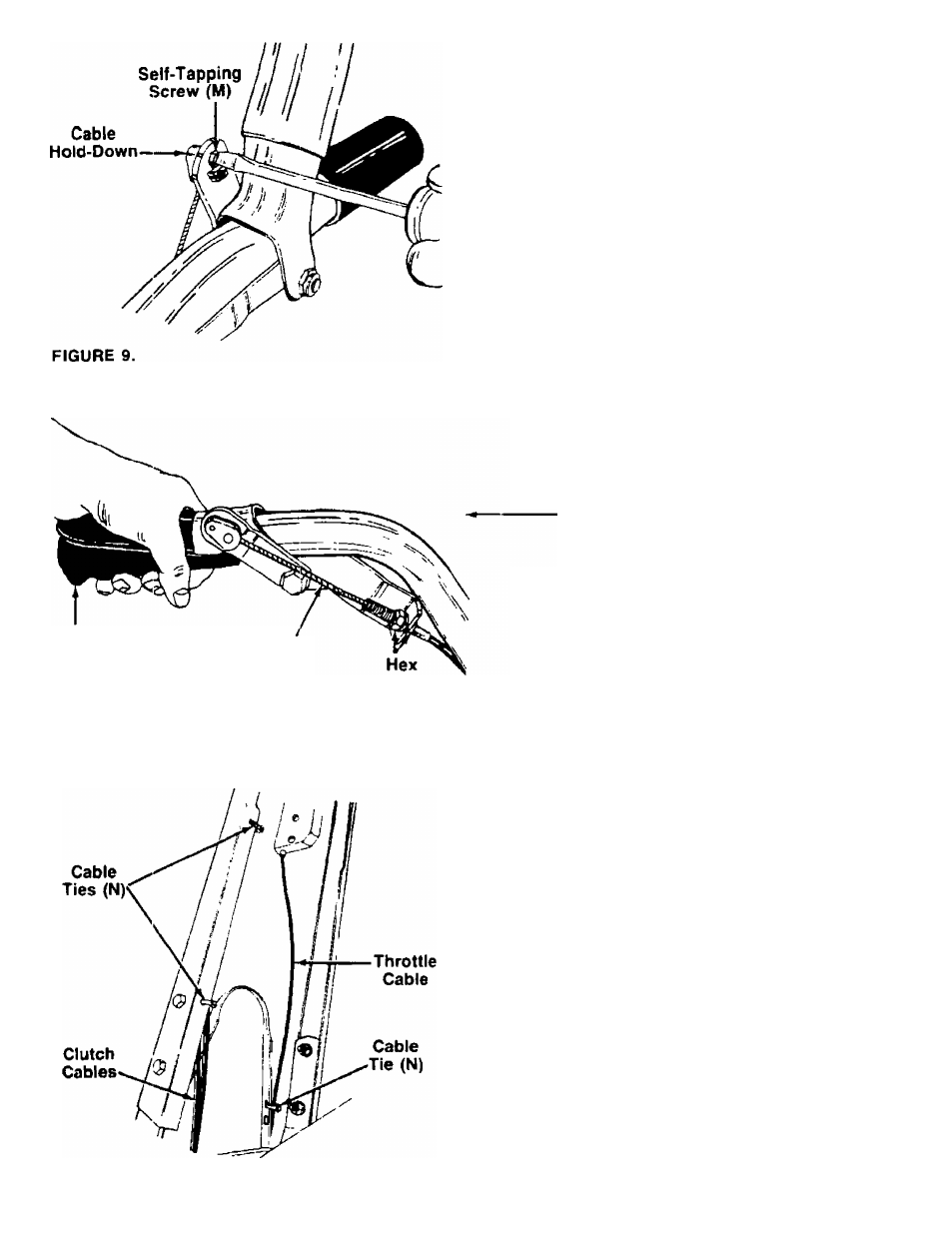
c.---Pull the cable upwards to obtain slack, lift the
left hanc clutch grip and insert the left hand
cable hold-down into the clutch grip. Secure
-----with self-tapping screw (M). See figure 9.
Clutch
Grip
FIGURE 10.
Control Wire
is Straight
With the clutch lever released (in the “up" posi
tion), adjust the bottom nut at the cable bracket
so there is only a slight amount of slack in the
control wire. Tighten the upper nut against the
bracket. Squeeze the clutch lever against the
handle. The control wire should now be straight.
See figure 10.
NOTE
Do not overtighten control wire. Too
much tension may cause it to break.
2. Attach the reverse clutch cable to the right handle
in the same manner, using the right hand cable
hold-down (L) (brown).
Ai
WARNING
X
■» »
The forward and reverse clutch cable
adjustment must be checked before
the unit is operated as instructed in
the Final Adjustment section on page 8.
3. Secure the control cables to the handle panel as
follows.
a. Secure the forward and reverse clutch cables
to the holes in back of the handle panel (left
hand side) using two cable ties (N) as shown
--------- in figure 11. Leave ties fairly loose.
b. Secure the throttle control cable to one of the
holes in the inside of the handle panel (right
hand side) as shown in figure 11. Leave tie fairly
loose.
4. Frim excess ends of cable ties.
FIGURE 11.