Assembly instructions, D—i i 0^1 – MTD 94-2105-B User Manual
Page 4
Attention! The text in this document has been recognized automatically. To view the original document, you can use the "Original mode".
NOTE
This unit is shipped WITHOUT GAS
OLINE or OIL. After assembly, see
separate engine section of this manual
for proper fuel and engine oil recom
mendations.
NOTE
Right and left hand is determined when
standing behind the titier in the operating
position.
D—I I 0^1
F-----
» G—
i
B-
FIGURE 1.
lO
Clevis
Pin (A)
Loosen
Bolt
ASSEMBLY INSTRUCTIONS
Tools Required for Assembly:
(2) M2" Wrenches or Sockets*
(2) 9/16" Wrenches or Sockets*
(1) Adjustable Wrench
(1) Phillips Screwdriver
(1) Flat Blade Screwdriver
‘The adjustable wrench may be used in piace of one
of the wrenches.
UNPACKING
Remove the tiller and loose parts from the carton. Make
certain all parts and literature have been removed
before the carton Is discarded.
Extend all control cables and place on the floor, Be
careful not to bend or kink control cables.
Parts in Carton:
Tiller
Handle Panel Assembly
Depth Stake
Tailpiece
Hardware Pack
‘Contents of Hardware Pack; (See Figure 1)
A (1)
B (4)
C
D
E
F
G
J
(3)
(
6
)
(
2
)
(
6
)
(
6
)
(
1
)
U-Clevis Pin
Hairpin Clips
Clevis Pins
Hex Bolts 3/8-16
X
1" Long
Belleville Washers 3/8" I.D.
Lock Washers 3/8" I.D.
Hex Nuts 3/8-16 Thread
Phillips Head Self-Tapping Screw
Hairpin Clip (B)
Depth Stake
Spring
K (1) Left Hand Cable Hold-Down (Black)
L (1) Right Hand Cable Hold-Down (Brown)
M (2) Self-Tapping Screws
N (3) Cable Ties
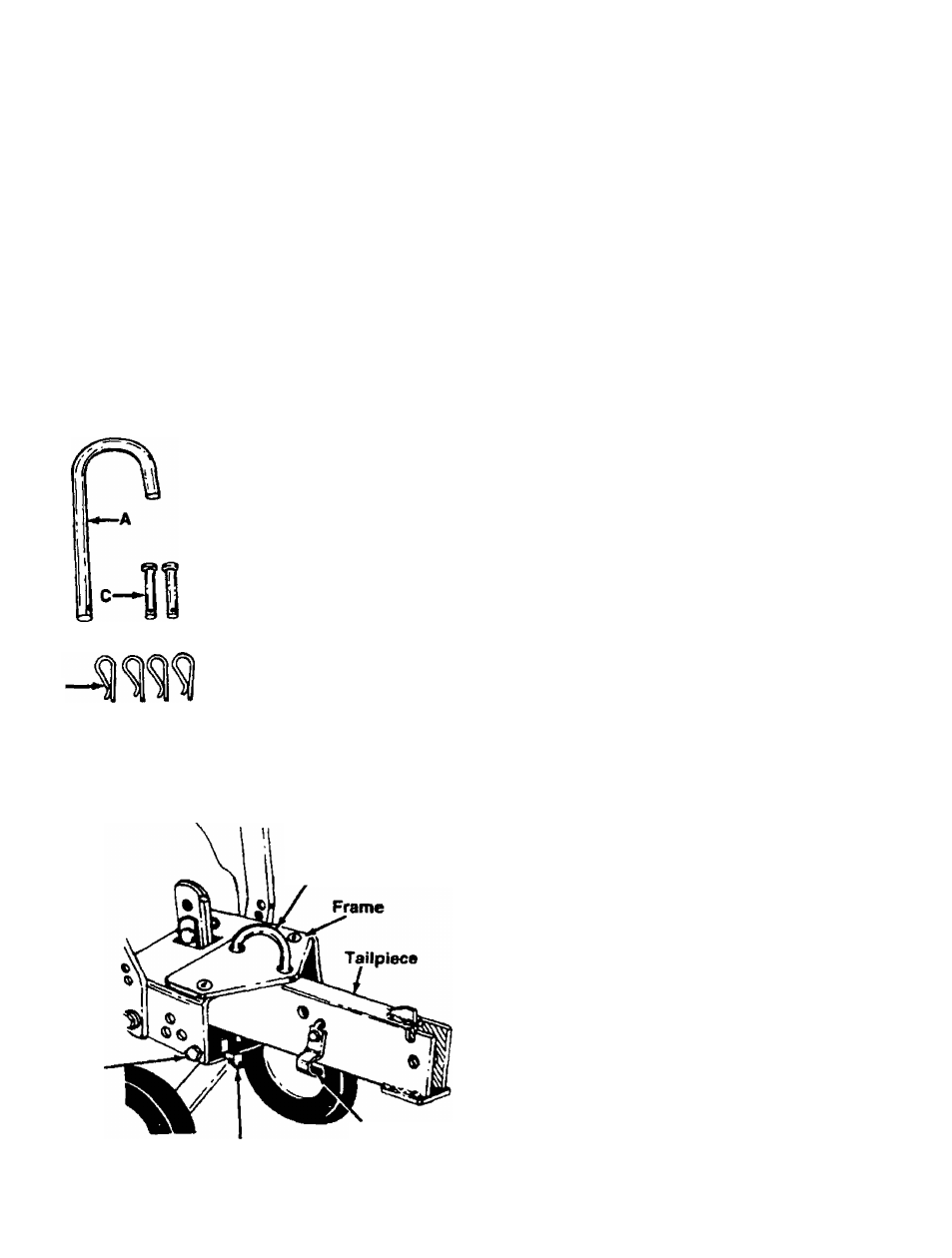
TAILPIECE INSTALLATION
Slide the tailpiece into the frame. If necessary, loosen
the two bolts on each side of the frame as shown in
figure 2 in order to insert the tailpiece. Secure with "U"-
devis pin (A) and hairpin clip (B). Tighten the bolts on
-the frame. See figure 2.
NOTE
The U-clevis pin which secures the
tailpiece can be set for two different
methods of operation. Refer to “Swinging
Tailpiece/Depth
Stake”
section
on
page 11.
FIGURE 2.