MTD 94-2105-B User Manual
Page 6
Attention! The text in this document has been recognized automatically. To view the original document, you can use the "Original mode".
Slot in
Cable Bracket
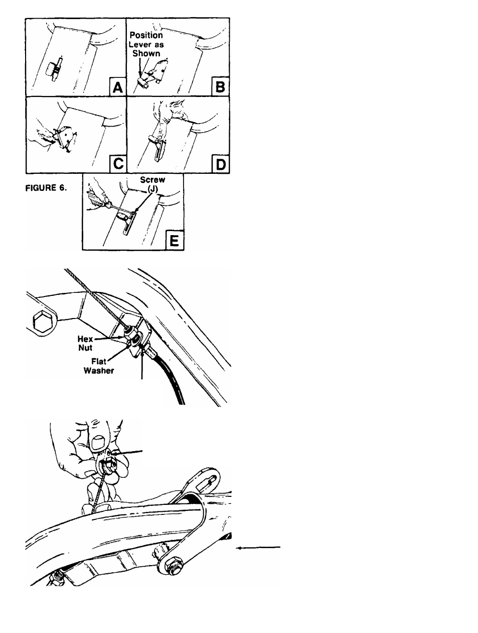
FIGURE 7.
Cable
’Hold-Down
(K) (Black)
THROTTLE CONTROL ASSEMBLY
The throttle control is already attached to the engine.
Assemble the throttle control to the handle panel as
follows (be careful not to kink the cable).
1. Route the throttle control cable between the han
dle mounting brackets. Hold the throttle control
assembly beneath the handle panel. Turn the con
trol sideways and insert the lever up through the
wide portion of the slot on the handle panel. See
——figure 6A.
2. After the end of the lever is through the slot, turn
and then tip the control forward as shown in figure
6B.
■^NOTE
The lever must be all the way to the
back of the control housing as shown
in figure 6B.
3. Slide the control completely through the slot as
shown in figure 6C.
4. Push the control back into the slot in the handle
panel and press in place. See figure 6D. Be cer
tain the control is locked securely into the slot.
5. Secure the throttle control to the handle panel
using
Phillips
head self-tapping screw (J). See
figure 6E.
ATTACHING THE CLUTCH CONTROL CABLES
The clutch control cables, already attached to the idler
brackets, are labeled FORWARD and REVERSE. The
left hand cable hold-down is black and is marked with
an “L.” The right hand cable hold-down is brown and
-is marked with an “R.” See figure 8.
1. Attach the forward clutch cable to the left handle
as follows (be careful not to kink the cable),
a. Remove one hex nut and flat washer from the
end of the casing on the forward clutch cable.
Slip the wire through the slot on the cable
bracket on the left handle. Push the end of the
casing up through the cable bracket. Rethread
the hex nut on the end of the cable. Do not
tighten at this time. See figure 7.
b. Hook the barrel end of the cable into the left
hand cable hold-down (K) (black). Slide the
cable around in the slot as shown in figure 8.
FIGURE 8.