Push block assembly – Sears 26462_0 User Manual
Page 9
Attention! The text in this document has been recognized automatically. To view the original document, you can use the "Original mode".
4. Repeat steps 1 through 3 for the other side of
the fence.
5. Make sure the adjustable jointing fence is inside the
router table fence as far as it will go and that the
clamping knob has been securely tightened.
FIGURE 14
FIGURE 16
A
warning
ATTACHMENT OF THE OVERHEAD GUARD TO
THE FENCE ASSEMBLY
1. Assemble the overhead guard to the router table
fence using two 1/4" pushnuts and the overhead guard
pivot pin, as shown in Figure 16.
2. Prior to inserting the overhead guard pivot pin, press
one of the pushnuts onto one end of the pivot pin. (It
may be necessary to tap the pushnut onto the over
head guard pivot pin with a hammer while supporting
the other end of the overhead guard pivot pin.)
3. Position the overhead guard on the fence so the
holes in the guard line up with the through-hole in the
router table fence. Make sure the orientation of the
overhead guard is as shown in Figure 16.
4. Insert the pivot pin through the aligning holes.
5. Press the second pushnut onto the other end of the
overhead guard pivot pin.
6. Move the guard up and down a few times to ensure
that it moves freely.
Once the overhead guard has
been assembled to the fence, DO NOT remove it
for any reason. Its removal can result in an unsafe
operating condition that can resuit in possibie
bodiiy injury.
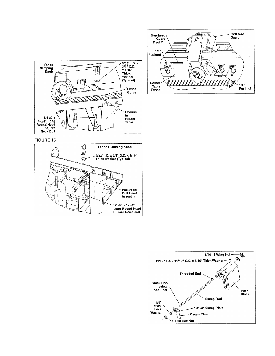
PUSH BLOCK ASSEMBLY
1. Thread the small end of the clamp rod into the
threaded hole of the clamp plate, until the rod bottoms
out securely against the plate.
2. MAKE SURE THAT THE CLAMP PLATE IS ORI
ENTED SO THAT THE “C” ON THE CLAMP PLATE
FACES OUTWARD.
3. Assemble the1/4" I.D. x 1/2" O.D. x 3/64" thick spring
lock washer and 1/4-28 hex nut to the clamp rod.
4. SECURELY TIGHTEN THE NUT ON THE CLAMP
ROD.
5. Insert the other end of the clamp rod through the
hole in the push block. MAKE SURE THE ORIENTA
TION OF THE PUSH BLOCK IS AS SHOWN IN FIG
URE 17.
6. Assemble the 11/32" I.D. x 11/16" O.D. x 1/16" thick
washer and the 5/16-18 wing nut to the clamp rod.
7. It is not necessary to tighten the wing nut. The
clamp rod should rotate freely in the clamp block.
FIGURE 17