Installation positions, Furnace installation, Dimensional information – Sears N8MPL050B12B1 User Manual
Page 6: Upflow
Attention! The text in this document has been recognized automatically. To view the original document, you can use the "Original mode".
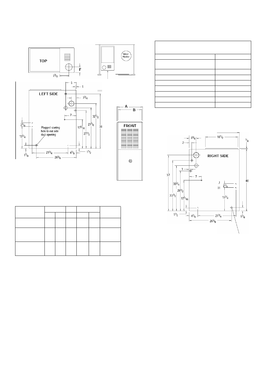
Figure 2
Dimensions and Clearances {*8MPIM/L Models)
MINIMUM CLEARANCES TO COMBUSTIBLE
MATERIALS FOR ALL UNITS
REAR
0
FRONT
(combustion
air
openings
in furnace and structure)
3”
Required For Service
*24”
ALL SIDES Of SUPPLY PLENUM
1"
SIDES
0
VENT
Single-Wall Vent
6"
Type B-1 Double Wall Vent
r
TOP OF FURNACE
r
•24" Min.
BOTTOM
*30" clearance recommended for furnace removal.
Horizontal position; Line contact is permissible only between lines
formed by intersections of top and two sides of furnace jacket, and
building joists, studs or framing,
281/2 -
23Vo
Drawing is representative some models may vary
4Vi6
DIMENSIOWS IN INCHES
DIMENSIONAL INFORMATION
Furnace
Model
Cabinet
Top
Bottom
Return Air
Opening
A
B
F
C
D
*8MPI\i/L050B12
‘8MPN/L075B12
I
5 V2
14
6
1^/s
12%
H
‘8MPN/L075F16
*8IVIPN100F14
•8MPN/L100F20
19Vg
1 7 5 / 8
7 3 / 4
1 4 3 / 4
J
•8MPN/L100J20
•8MPN/L125J20
•8MPN150J20
2 2 3 / 4
2 1
I
/ 4
9 I/ 2
1 3 3 / 4
J
NOTE;
Evaporator "A” coil drain pan dimensions may
vary from furnace duct opening size. Always consult
evaporator specifications for duct size requirements.
Furnace is designed for bottom return or side return.
Return air through back of furnace is NOT allowed.
Plugged starting hole to
cut side duct opening
Denotes Brand
Installation Positions
This furnace can be installed in an upflow, horizontal (either left or
right) or downflow airflow position. DO NOT install this furnace on
its back. For the upflow position, the return air ductwork can be at
tached to either the left or right side panel and/or the bottom. For
horizontal and downflow positions, the return air ductwork must be
attached to the bottom. The return air ductwork must never be at
tached to the back of the furnace.
Furnace Installation
Inspect the rating plate to be certain the model number begins with
"N8MP" or "’8MP". This identifies the unit as a multi-position fur
nace and can be Installed in a Upflow, Horizontal Right, Horizontal
Left or Downflow position.
’ Dentoes Brand (C, H, T)
Upflow
No modifications are required for upflow installation. (See
Figure 3)
441 01 2613 02
- N8MPL075B12B1 8MPL050B12B1 N8MPN100J22B1 N8MPL125J20B1 8MPL075F16B1 N8MPN100F14B1 N8MPL100J22B1 8MPN125J20B1 N8MPN075F16B1 8MPN075B12B1 N8MPN125J22B1 8MPN100F14B1 8MPN100F20B1 N8MPN125J20B1 N8MPL100F20B1 8MPL075B12B1 8MPL125J20B1 N8MPN050B12B1 8MPN050B12B1 N8MPL125J22B1 8MPN075F16B1 8MPN150J20B1 8MPN100J20B1 N8MPN075B12B1 N8MPL075F16B1 8MPL100F20B1 N8MPN100F20B1 8MPL100J20B1