Checks and adjustments, Gas supply pressure, Manifold gas pressure adjustment – Sears N8MPL050B12B1 User Manual
Page 27: Warning
Attention! The text in this document has been recognized automatically. To view the original document, you can use the "Original mode".
Duct Design and Duct Installation Requirements
See Section 10.
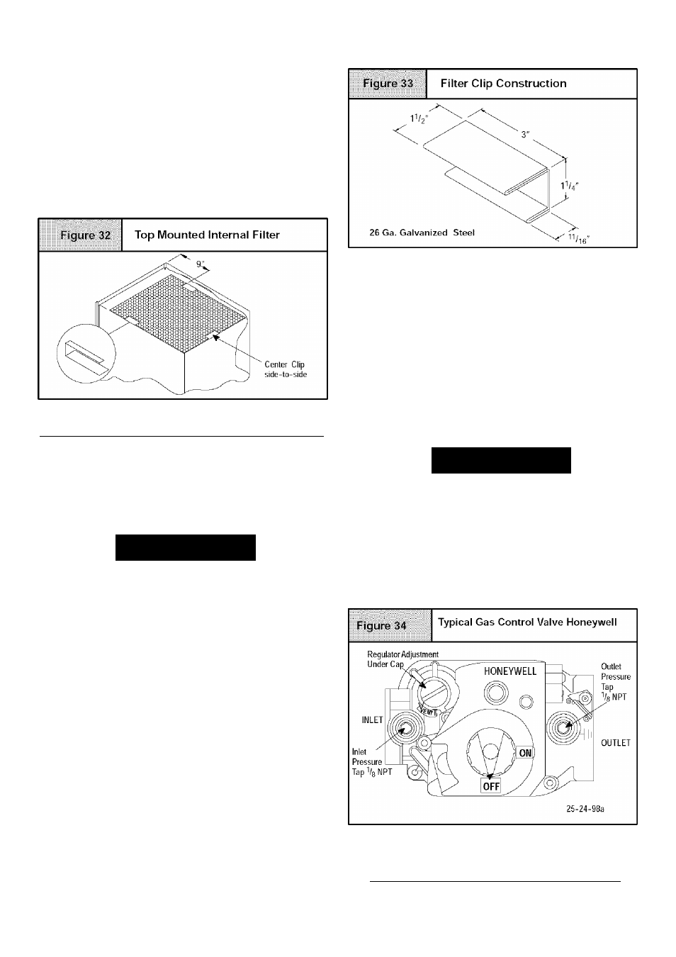
Internal Filter in Top Return Installation
When installing top-mounted filter inside the furnace, install the fil
ter clips on the edge of the top duct opening with the wider end of
the clips toward the blower as shown in Figure 32. Clips may be
obtained from your distributor or fabricated from sheet metal
(Figure 33). Insert filterintoside clips firstand push filter back until
it is fully engaged into back clip.
NOTE: If filters are only suitable for heating application, ad
vise homeownerthat filter size may need to be increased if air
conditioning is added.
Addition Of Air Conditioning
See Section 10.
12. Checks and Adjustments
Startup
NOTE: Refer to startup procedures in the Users Information
Manual.
WARNING
ELECTRICAL SHOCK, FIRE, OR EXPLOSION
HAZARD.
Failure to follow safety warnings exactly could
result in death, personal injury and/or property
damage.
If any sparks, odors or unusual noises occur,
immediately shut OFF gas and power to furnace.
Check for wiring errors or obstruction to blower.
Gas Supply Pressure
Gas supply pressure should be within minimum and maximum val
ues listed on rating plate. Pressures are usually set by gas suppli
ers.
(See LP Gas Conversion Kit instruction manual for furnaces con
verted to LP gas.)
Manifold Gas Pressure Adjustment
NOTE: Make adjustment to manifold pressure with burners oper
ating^_________________________________________________
WARNING
FIRE OR EXPLOSION HAZARD.
Failure to turn OFF gas at shut off before connecting
manometer could result in death, persona! injury
and/or property damage.
Turn OFF gas at shut off before connecting
manometer.
1. With gas OFF, connect manometer to manifold pressure tap
on outlet of gas control valve. See Figure 34. Use a manome
ter with a
0" to 12 " water column range.
2.
Turn gas ON. Operate the furnace by using ajumper wire on
the R to W thermostat connection on the control.
3.
Remove manifold pressure adjustment screw cover on fur
nace gas control valve. Turn adjusting screw counterclock-
441 01 2613 02
- N8MPL075B12B1 8MPL050B12B1 N8MPN100J22B1 N8MPL125J20B1 8MPL075F16B1 N8MPN100F14B1 N8MPL100J22B1 8MPN125J20B1 N8MPN075F16B1 8MPN075B12B1 N8MPN125J22B1 8MPN100F14B1 8MPN100F20B1 N8MPN125J20B1 N8MPL100F20B1 8MPL075B12B1 8MPL125J20B1 N8MPN050B12B1 8MPN050B12B1 N8MPL125J22B1 8MPN075F16B1 8MPN150J20B1 8MPN100J20B1 N8MPN075B12B1 N8MPL075F16B1 8MPL100F20B1 N8MPN100F20B1 8MPL100J20B1