Sears 113.2945 User Manual
Page 6
Attention! The text in this document has been recognized automatically. To view the original document, you can use the "Original mode".
BOTTOM SIDE OF TABLE
T-NUT CORRECTLY INSTALLED
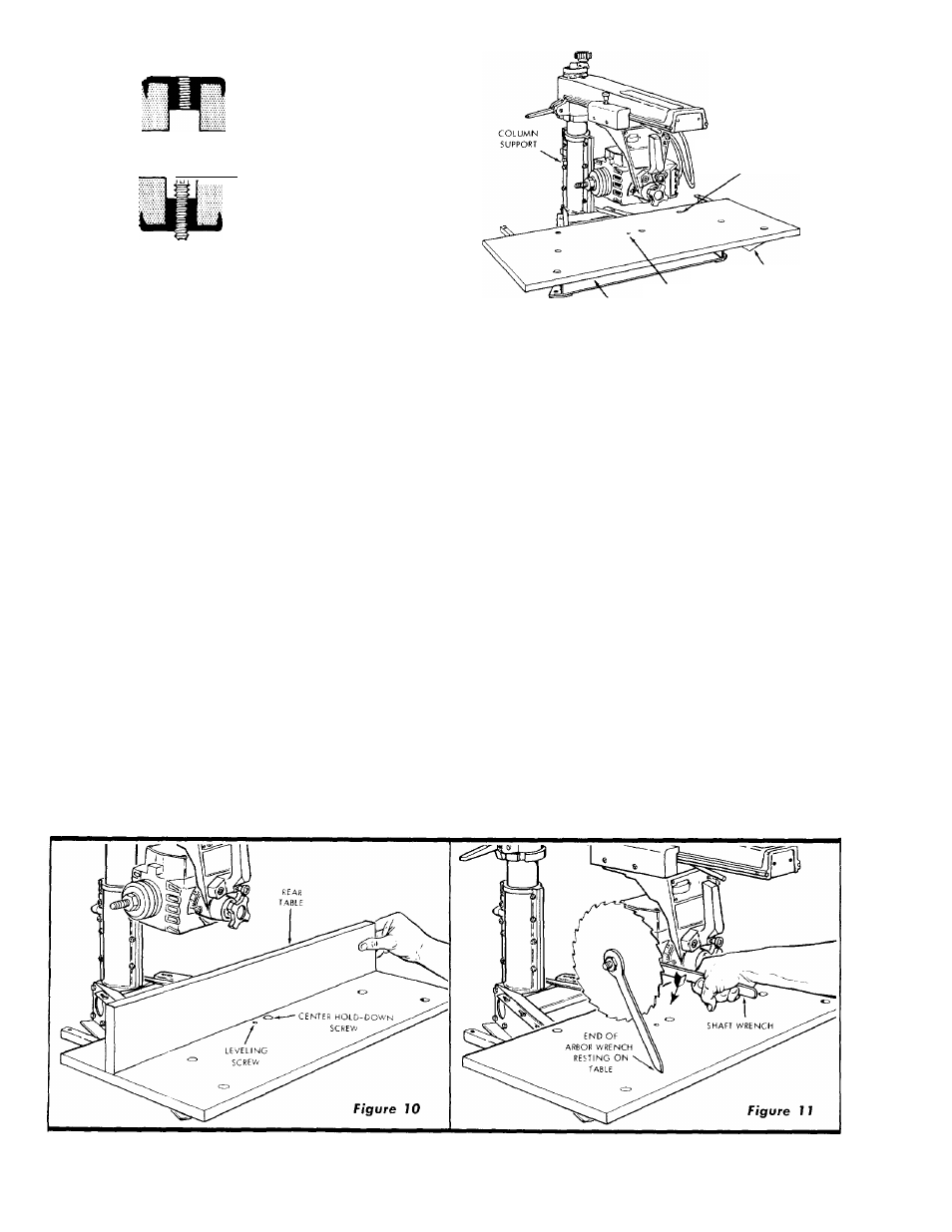
LEVELING SCBEW .
\ TOP OF TABLE
REAR TABLE
SUPPORT BRACKET
FRONT
TABLE
LEVELING SCREW INSTALLED
IN T-NUT
J;
SCREW
(No. 10 X S/B IN.)
HOLE FOR TABLE
HOLD-DOWN SCREW
(SEVEN,TOTAL)
Figure 8
R.H. TABLE SUPPORT
FRONT TABLE
LEVELING SCREW
HOLE
Figure 9
3. Loosen keylocking bolts (See figure 7) and insert a 3/16-
inch Hex-L wrench into the socket-head set-screw that
adjusts the column tube wedge key, as shown in figure 7.
Rotate the set-screw slowly in (clockwise) until no side
play can be felt in radial arm.
4. Check for binding by rotating the elevation crank. If the
crank rotates with noitceable resistance, loosen the set
screw by rotating the Hex-L wrench counterclockwise
until rotation is normal. An effective method for finaliz
ing the set-screw adjustment is to rotate the screw while
the elevation crank is being rotated, checking for side
play in radial arm as the adjustment progresses. The
adjustment is correct when all side play of radial arm
Is eliminated and only very slight additional resistance
can be felt when rotating the elevation crank.
5. If some radial arm side play can still be detected after
performing the above adjustment, it will be necessary
to adjust the forward five screws through the right-,
and left-hand column supports as follows;
a. While rotating the elevation crank, tighten the five
column adjusting screws slightly at the forward edge
of column supports. Each screw should be tightened
only slightly, and each one the same amount, until
a slight resistance can be felt when rotating the
elevation crank, then each screw backed off just
enough to restore a normal feel to the elevation
crank.
b. Recheck the adjustment of the column tube wedge
key set-screw as outlined in preceding instructions.
6. After the above adjustments have been completed, re
check the radial arm for absence of side play.
7. When all side play has been eliminated, lock the column
tube key in place by tightening keylocking bolts. (See
figure 7.)
STEP THREE-INSTALLATION OF FRONT TABLE
1. Place the large (front) table board upside-down on floor.
Distinguish between the one through-bored (leveling
screw) hole near the center of the board, and the seven
counterbore holes. The counterbores are in the top sur
face of the board. Drive the T-nut into the through-hole.
(See figure 8 which shows the T-nut installed.)
2. With the front table board still in the upside-down posi
tion, locate the two pre-drilled screw holes near each
end of the table. Attach the two rear table support
brackets to the table with two No. 10 x 5/8-inch screws
in each bracket. (See figure 8.)
3. Place the 1/4-20 U-clip nut on the base cross member
to receive the center front table attaching screw.
4. Place the large, front table board on the table supports.
(See figure 9.)
5. Align the counterbore holes with matching holes in table
supports.
6. Place a 17/64-inch plain washer and a l/4-20x 1-inch
pan-head machine screw from loose parts pack in each
of the six counterbore holes located above the table
supports. Use a l/4-20x 1-1/4-inch pan-head machine
screw in counterbored hole at the center of the table
board.