Motor safety protection, Mounting the saw on a work bench, Alignment instructions – Sears 113.2945 User Manual
Page 4
Attention! The text in this document has been recognized automatically. To view the original document, you can use the "Original mode".
MOTOR SAFETY PROTECTION
The saw motor is equipped with a manual-reset thermal
overload protector, designed to open the power line circuit
when the motor temperature exceeds a safe value.
1. If the protector opens the line and stops the saw motor,
press the saw switch to the "OFF” position immediately
and allow the motor to cool.
2.
After cooling to a safe operating temperature, the
overload protector can be closed manually by pushing
in the red button on the motor cover and nameplate. If
the red button will not snap into place immediately, the
motor is still too hot and must be allowed to cool for a
while longer. (An audible click will indicate protector
is closed.)
3. As soon as the red button will snap into running position,
the saw may be started and operated normally by
pressing the saw switch to the "ON" position.
4. Frequent opening of fuses or circuit breakers may result
if motor is overloaded, or if the motor circuit is fused
with a fuse other than those recommended. Do not use
a fuse of greater capacity without consulting the power
company.
5. Although the motor is designed for operation on the
voltage and frequency specified on motor nameplate,
normal loads will be handled safely on voltages not more
than 10% above or below the nameplate voltage. Heavy
loads, however, require that voltage at motor terminals
be not less than the voltage specified on nameplate.
6. Most motor troubles may be traced to loose or incorrect
connections, overloading, reduced input voltage (which
results when small size wires are used in the supply
circuit) or when the supply circuit is extremely long.
Always check connections, load and supply circuit when
the motor fails to perform satisfactorily. Check wire
sizes and lengths with the table in the next paragraph.
IMPORTANT: The following wire sizes are
recommended for connecting the motor to
power source for trouble-free operation.
Length of
Wire Size Required
Conductor
(American Wire Gauge No.)
50 feet
or less ......................................No. 12
100 feet
or less....................................... No. 10
100 feet
to 150 feet................................ No. 8
150 feet
to 200 feet................................ No. 6
200 feet
to 400 feet................................ No. 4
For circuits of greater length the wire size must be in
creased proportionally.
MOUNTING THE SAW ON A WORK BENCH
The saw should be placed on a suitable sturdy work bench,
or Craftsman Power Tool Bench. The base of the saw must
be mounted flush to a flat surface on the work bench to
prevent distortion of the saw base. The nuts, screws, and
washers which attach the wooden shipping skids to the
saw base may be used to secure the saw base to the work
bench, or tool bench.
ALIGNMENT INSTRUCTIONS
NOTE: The seven basic "steps" that follow are
essential in order to insure correct saw table
alignment.
WARNING: Make sure the power cord is
not plugged into an electrical outlet when
working on the saw.
STEP ONE - INSTAllATION AND ADJUSTMENT
OF TABLE SUPPORTS
1. Place the saw on a work bench or table.
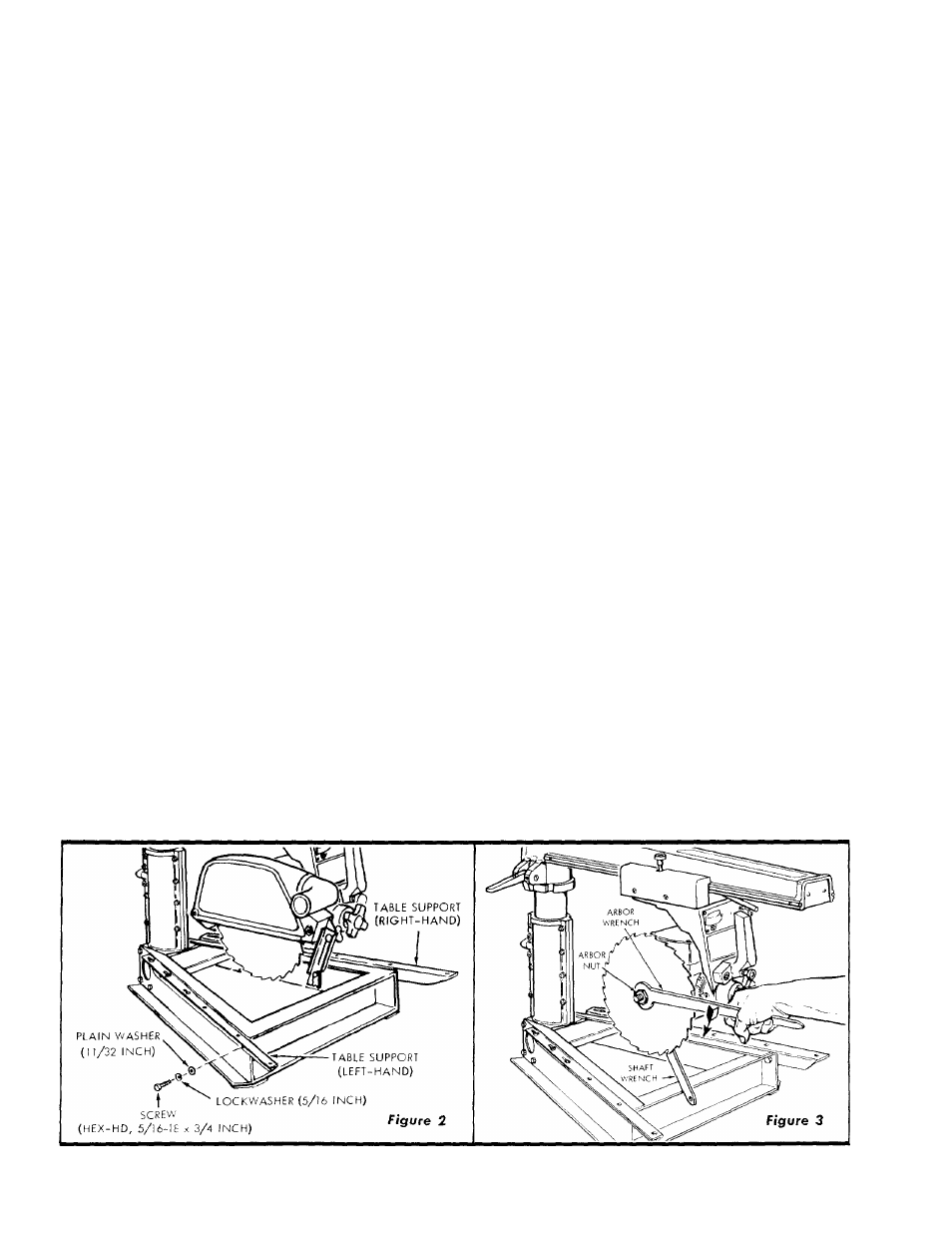
2. Attach right-, and left-hand table supports to the saw
base as follows: (See figure 2.)
NOTE: Right-, and left-hand supports may be
identified by the three "keyholes" in the table
attaching surface of each support. These key
holes are for attaching the table clamps and
are located at the rear of the saw. Also, the
angle of each support turns outward, away
from the saw base. (See figure 2.)
a. Place one 5/16-inch, split lockwasher and one 11/32-
inch plain washer an each of the four 5/16-18 x 3/4-
inch, hex-head screws, all from the loose parts pack.
b. Attach each table support to the saw base with two
of the hex-head screws, lockwashers and plain wash
ers assembled in preceding step.
c. Position each support on the base so each screw is
approximately centered in the slotted hole in the
support.
d. Tighten the screws just enough to hold the table
supports in position, but loose enough to slip against
the base channel when tapped with a plastic mallet.
3. Adjust Table supports parallel to radial arm as follows:
a. Loosen the guard clamp screw and remove the guard.
b. Lock carriage and hold the motor shaft (at inner edge
of saw blade) with the shaft wrench and loosen the