Electrical data table 15 — electrical data (60-hz) – Carrier 38BA User Manual
Page 18
Attention! The text in this document has been recognized automatically. To view the original document, you can use the "Original mode".
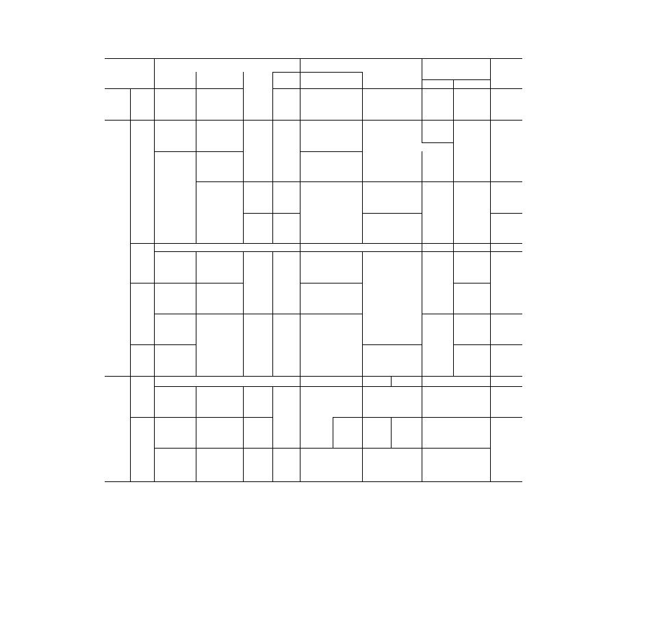
ELECTRICAL DATA
Table 15 — Electrical Data (60-Hz)
MODEL
38
UNIT
EACH COMPRESSOF
A
FANS
”FLA'(eor
MAX
FUSE
AMPS
Nameplate
Voltage
Voltage
Range
MWA
51
31
28
14
ICF
FLA
LR
No. 1
No. 2
GR
006
230*
200
230
460
208-254*
180-220
208-254
416-508
157
1 12
102
51
39 0
23.0
20 5
10.3
155 0
110 0
100 0
50 0
2 0
2.0
2 0
1 3
-
60
40
35
20
200
180-229
42
135
29 1
i'32
3.2
50
230
207-264
37
127
25 4
124
3 2
-
45
460
414-528
18
64
12.7
62
1 6
_
25
BA
575
518-660
14
53
10 2
50
3.2
20
200
180-229
54
167
39.6
164
3 2
-
70
230
207-264
48
156
34 4
153
3.2
60
460
414-528
24
79
17.2
77
1 6
—
30
575
518—660
19
65
13 8
62
"3>2 f
-
25
200
180-229
68
198
49 3
191
3 2
3 2
80
230
207-264
62
179
44.3
172
3 2
3 2
80
460
414-528
31
89
22 2
86
1 6
1 6
35
575
518-660
24
71
17.9
69
1 0
1 0
30
200
180-229
86
184
63 6
2 5 6 / 1 7 3
3 2
3 2
100
230
207-264
78
166
57 2
2 4 0 / 1 6 0
3 2
3 2
90
460
414-528
39
123
28 6
120
1.6
1.6
45
575
518-660
32
99
22 9
96
1.0
1 0
35
No. 1
No. 2,3
200
180-229
86
184
64.0
256/i73
3 2
3.2
100
230
207-264
78
170
58 0
2 4 0 / 1 6 0
3 2
3 2
90
460
414-528
39
123
29 0
120
1 6
1 6
45
AD
575
518-660
32
99
23 0
96
1 0
1 0
40
200
180-229
122
216
85 8
345/202
4 5
4 5
150
230
207-264
103
204
71 5
3 0 0 / 1 9 0
4 5
4 5
125
460
414-528
50
156
37 5
150
1 9
1 9
60
575
518-660
41
125
28 6
120
1 6
1 6
50
200
180-229
175
290
123 0
471/27i
6 2
6 6
200
230
207-264
154
273
108 6
410/255
6 2
6 0
175
460
414-528
77
137
54.4
2 0 5 / 1 2 8
3 0
3 0
90
575
518-660
62
172
43 6
164
2 4
2 4
70
200
180-229
175
338
123 0
5 0 6 / 3 1 9
6 2
6 6
200
230
207-264
158
318
111 4
4 4 0 / 3 0 0
6 2
6 0
200
460
414-528
81
159
57 2
2 2 0 / 1 5 0
3 0
3 0
90
575
518—660
63
184
45 0
176
b 4
2.4
80
No. 1
No. 2
No. 1
No. 2
(No.) FLA (eo)
200
180-229
210
447
85 8
345
(4) 4 8
225
230
207-264
182
389
74 3
300
(4) 4 2
200
460
414-528
93
195
37 9
150
(4) 2 1
100
575
518-660
74
156
30 0
120
(4) 1 7
80
200
180-229
259
486
124 4
85 8
506
345
(6) 4.8
300
230
207-264
225
424
108 6
74 3
440
300
(6) 4 2
250
460
414-528
116
214
56.5
37 9
220
150
(6) 2 1
125
575
518-660
93
171
45 0
30 0
176
120
(6) 1 7
100
200
180-229
298
646
•124 4
506
(6) 4 8
350
230
207-264
259
564
108.6
440
(6) 4.2
300
460
414-528
135
284
56 5
220
(6) 2 1
150
575
518-660
108
227
45 0
176
(6) 1 7
125
Amp draw at 230 volts The units have a 575-v to 230 v
transformer and use a 230-v motor.
Full Load Amps
Maximum Instantaneous Current Flow during starting
(sum of LRA for last compressor to start plus the FLA
for all other motors in unit)
Locked Rotor Amps
V a l u e s i n i t a l i c s
are for the first
winding where the motoi is wired for part-winding start
The greater value is the full LRA See Note 1
— Minimum Wire Amps Complies with National Electrical
Code (NEC), Section 430-24.
Voltage Range -
Units are suitable for use on electrical systems
where voltage supplied to the unit terminals in not
below or above the listed range limits Maximum
allowable voltage unbalance between phases is 2 percent
FLA
ICF
LRA -
MWA
*Single Phase; all others are 3 Phase
NOTES:
1 Maximum incremental current inrush during starting is the full
LRA for the largest compressor motor in the unit when wired
for across-the-line starting, or the LRA drawn by the first
winding of the largest compressor when the motor is wired for
part-winding start.
2 Compressors are numbered from left to right, viewed from the
compressor end of the unit
3
On 38AD units, no 1 fan is adjacent to the compressor
compartment On 38AE units, fans no 1 and 2 are adjacent to
the compressoi compartment
4
On all units, fans adjacent to the compressor compartment
have single-phase speed control motors on 200-, 208- and 230-v
units, suitable for use with 32 Series Motormaster® head
pressure control On 38AE, 460-v units, the fans adjacent to
the compressors have speed control motors, suitable for use
with Motormaster control On 38BA and 38AD012—01 6 units,
speed control motors are supplied in the no 1 fan location
18