Lgth of interconnecting piping – Carrier 38BA User Manual
Page 15
Attention! The text in this document has been recognized automatically. To view the original document, you can use the "Original mode".
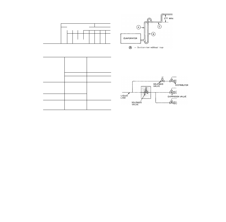
Table 12 — Refrigerant Piping Sizes
(Double Suction Riser)
LGTH OF INTERCONNECTING PIPING
CONDENSING
26-50
51-75
76-100
UNIT
L ine Size ( n. OD)
A
B
C
A
B
C
A
B
C
38AD034
_
_
_
_
_
2%
l=/8 2 Vs
38AE044
-
—
2%
1%
2%
2\
1%
2 Vs
38AE054
2Vs
2%
2%
1%
2%
2\
2%
2 Vs
NOTE: Double Suction Risers are sized according to the equal area
method and are based on standard unloading available
Table 13 — Liquid Line Data
MAXIMUM
FILTER-DRIER
AND
SIGHT GLASS
CONN. SIZES
(in. flare)
CONDENSING
UNIT
ALLOWABLE
LIQUID
LIFT (ft)
38GR006
90
Vs
38BA008
60
Vs
38BA009
45
V
38AD012
71
Vs
38AD014
46
Vs
38AD016
70
Vs
38AD024
84
Vs
38AD028
64
5/
5
® See Note 2
/a
38AD034
46
38AE044
73
38AE054
38
See Note 3
38AE064
56
NOTES
1 Maximum allowable liquid lift is based on 7 psi pressure
drop for accessories and a 2 F liquid line loss
2
Units 38AD028 and 034 have 2 filter-driers and one sight
glass All other units have one of each
3 Filter-driers and sight glasses are factory supplied except
for the 38AE units Connections are for both ends
CONDENSING
UNIT
@
— Suction riser
with
trap
©
— Suction line to condensing unit
Fig. 2 — Suction Line Piping
Liquid line solenoid valve serves 2 coils
Fig. 3 — Location of One Liquid Line
Solenoid Valve Serving 2 Coils
15