Aleo, Sporian, Table 11 — refrigerant piping sizes – Carrier 38BA User Manual
Page 14: Lgth of interconnecting piping 51-75776-100
Attention! The text in this document has been recognized automatically. To view the original document, you can use the "Original mode".
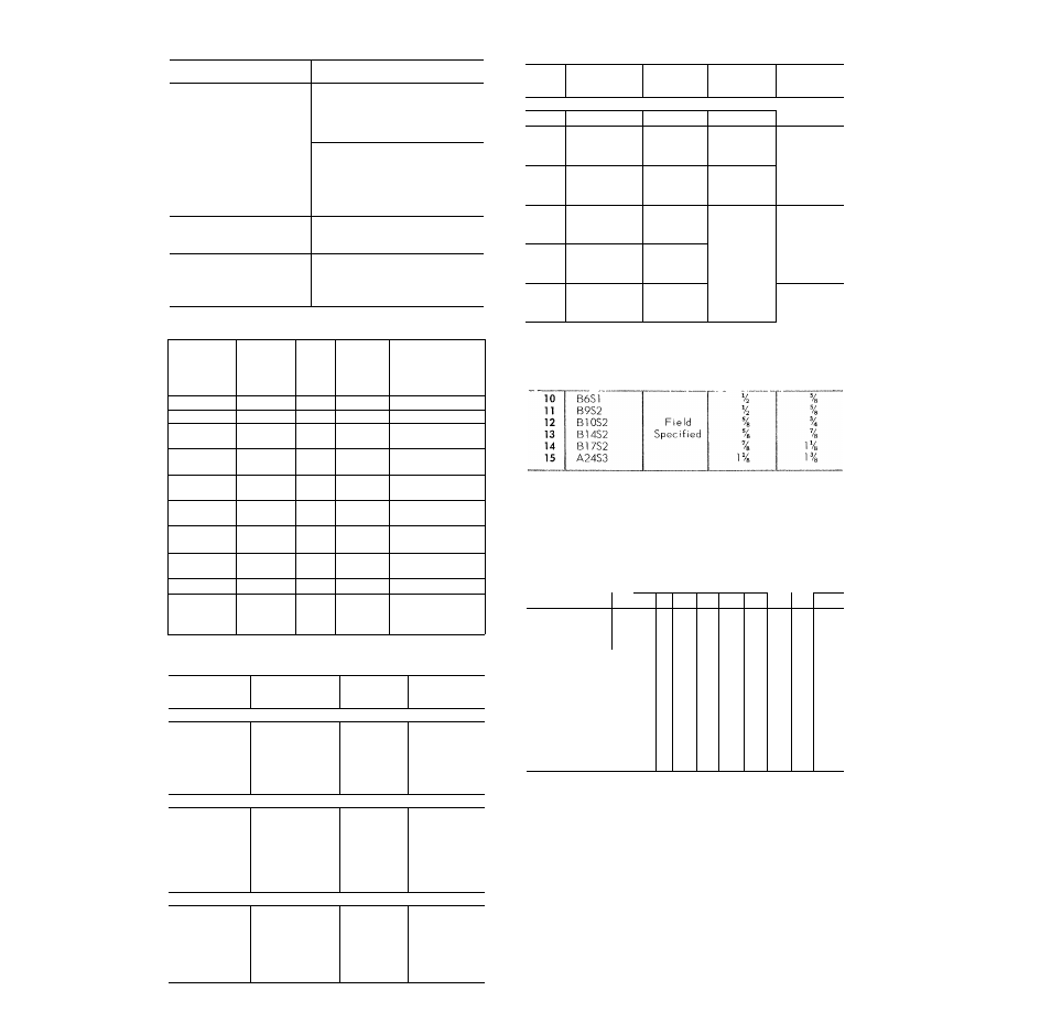
Table 7 — Nozzle Part Numbers
Table 10 — Solenoid Valve Selection Key
NOZZLE TYPE
CARRIER PART NO.
C4
EA19CZ904
C8
EA19CZ907
CIO
EA19CZ908
C12
EA19CZ909
C15
EA19CZ910
G2'/2
EA19CY902
G3
EA19CY903
G4
EA19CY904
G5
EA19CY905
G6
EA19CY906
G8
EA19CY907
E5
EA09ZC010
E6
EA09ZC012
E8
EA09ZC016
J3
EA19CW904
J4
EA19CW905
J5
EA19CW906
J6
EA19CW907
Table 8 — Nozzle and Distributor Data
FAN-COIL
UNIT
EVAP
SECTION
COIL
FACE
AREA
(sq ft)
NOZZLE
DISTRIBUTOR*
CONN.
(in.)
40BA009
Upper
7 12
J4
%
F lore
40RR008
Upper
7 22
J5
%
Flore
40RR012
Upper
Lower
3 83
6.87
G4
G6
V
40RR016
Upper
Lower
8 45
8 45
G5
V
40RR024
Upper
Lower
9 60
8.44
G8
Va
40RR028
Upper
Lower
14.50
8.13
C15
E8
iVa
40RR034
Upper
Lower
14 50
12.40
C15
Hi
4 OR R 044
Upper
Middle
14.10
14 10
CIO
1%
Lower
8 28
G8
Vs
40RR054
Upper
Middle
Lower
16 05
16.05
14 10
CIO
P/a
*Sporlan distributors are factory instailed and require Sporian nozzles.
Table 9 — Thermal Expansion Valve Selection Key
KEY
LETTER
PART NO.
INLET
(in.)
OUTLET
(in.)
Carrier
A
EA025C322
%
V
/8
В
EA035C370
Ve
C
EA025C362
‘6
Ve
D
EA025C423
%
V
/8
E
EA03 PC461
%
Ve
R
EA03PC503
Va
IVe
Aleo
F
TCLE300HW
Уа
V
78
G
TCLE400HW
V
2
Ve
H
TCLE500HW
Va
Ve
1
TCLE700HW
V
Ve
J
TCLE900HW
Va
V
/8
К
TJR1400HW
Va
V
78
L
TJR1800HW
%
V
78
Sporian
M
SVE-3-GA
%
5/
78
N
SVE-4-GA
Va
V
78
0
SVE-5-GA
Va
y
78
P
SVE-8-GA
Ve
y
Q
PVE-ll-GA
Va
Ve
R
PVE-16-GA
Ve
iVe
KEY
NO.
PART NO.
VOLTAGE
INLET
ODF (in.)
OUTLET
ODM (rn.)
Carrier
1
EFl 1BS182
115
Va
Ve
ÉFUBSIOI
115
2
EFl1BS193
208
Va
Ve
E F11 BS195
230
EFl 1BS221
115'
3
EFl 1BS223
208
Ve
V
74
EFl1BS225
230
EF11BS231
1 15
4
EFl 1BS233
208
Ve
Ve
EF11BS235
230
EF11BS281
115
5
EFl 1BS283
208
Ve
iVe
EFl 1BS285
230
EF11BS341
1 15
6
EFl 1BS343
208
iVe
IVe
EF11BS345
230
230RA8S5
230RA9S7
230RA12S7
Aleo
Field
Specified
Sporian
Table 11 — Refrigerant Piping Sizes
CONDENSING
UNIT
LGTH OF INTERCONNECTING PIPING
51
-
75776-100
0-15
16-25
26-50
Line Size (in. OD)
LÍ
s
L
s
L
s
L
s
L
s
38GR006
%
Va IVe
Va
IVe
Va
H/e
V
78
H/e
38BA008
Va IVe
Va
H/e
Ve
H/e
V
78
H/e
38BA009
Va IVe
Ve
H/e
Ve
H/e
5/
78
H/e
38AD012
Va IVe
Ve
H/e
V
78
H/e
V
78
H/e
38AD014
1
n
Va H/e
V
78
H/e
V
78
H/e
y
78
H/e
38AD016
vA
Hi
Ve IVe
V
/8
H/e
V
78
H/e
7
78
2 Ve
38AD024
%\
Hi
Ve IVe
V
78
H/e
Ve 2 Ve
Ve
2Ve
38AD028
%\
1%
Ve iVe
7/
78
2Ve
Ve
2Ve
Ve
2Ve
38AD034
’s7\
Ve 2Ve
Ve 2Ve
Ve
2Ve
H/e
*
38AE044
2%
Ve 2Ve
Ve 2Ve
IVe
*
H/e
*
38AE054
2V»
Ve 2Ve
iVe
*
H/e
*
H/e
*
38AE064
2
Ve Ve 2Ve
IVe
2 Ve
H/e
2 Ve
H/e 2 Ve
. C ose coupled
L — Liquid
S
— Suction
•Requires double suction riser, see Table 12.
NOTES:
1
Pipe sizes are based on a 2 F loss for liquid lines and a 1 5 F
loss for suction lines If the suction line is piped according to
Fig. 5 which results in a 0 5 F line loss, the pipe sizes given
result in total suction line loss of 2 F
2
Pipe sizes are based on an equivalent length equal to the
maximum length of interconnecting piping plus 50 percent
for fittings A more accurate estimate may result in smaller
sizes and eliminate the need for a double-suction riser
3
If units are close coupled, add 2 percent to combination
ratings
4. Units should be charged in accordance with the Installation
Instructions
14