Unit controls and safety devices – Carrier 38ED User Manual
Page 9
Attention! The text in this document has been recognized automatically. To view the original document, you can use the "Original mode".
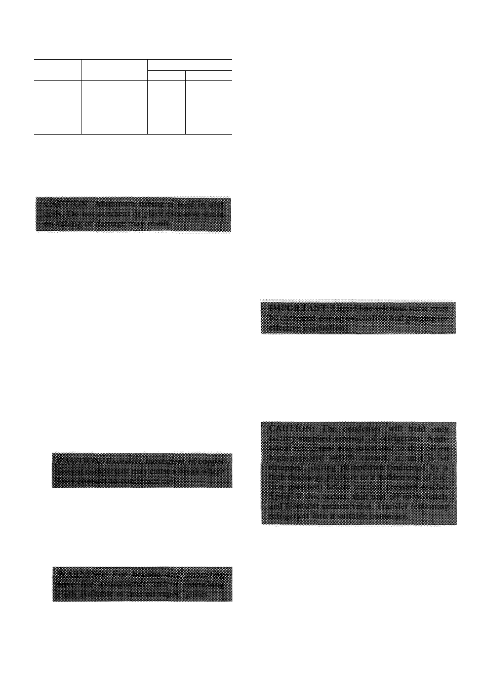
Table 8 — Compressor Data
MODEL
38ED
PRODUCTION
COMPRESSOR*
OIL CHARGE (oz)t
Initial
Recharge
018
AB5515H
32
30
024
CRC-1
55
51
030
CRE-1
55
51
036
AV5532H
54
50
042
AV5538E
54
50
048
AV5546E
54
50
060
PC60
66
64
numbers
fWhere piping exceeds 50 ft, contact your local Carrier distributor
Follow safety codes. Wear safety glasses and
work gloves. Have quenching cloth available.
1. Remove top cover by loosening screws around
unit and screws in connector plate. Lift cover
straight up.
2. Disconnect high- and low-voltage field wiring
and fan motor leads from capacitor and
contactor.
3. Remove screws holding discharge grille in place.
Lift grille from unit.
4. Disconnect compressor leads (crankcase heater,
low-pressure switch, if so equipped) from elec
trical components and pull them thru the wire
access opening into the coil section. Lift fan
orifice/control ring after pinching and pressing
down on 3 plastic pins of tube supports.
5. Remove louvered casing by taking out 16 screws
securing it to the cabinet and sliding it away
from the eoil.
6. Using a midget tubing cutter, cut liquid and
discharge lines on the coil and suction line at a
convenient place for easy reassembly with
copper slip couplings.
8
.
7. After plugging connections, remove condenser
coil by pinching plastic pins of tube supports
that extend into basepan and lift vertically. Set
coil on a clean, flat surface.
Remove compressor holddown bolts and slide
out compressor. Remove crankcase heater, if so
equipped.
9. Carefully unbraze suction and discharge line
piping stubs from compressor after noting posi
tion of stubs to assist when reinstalling.
10. Install new compressor, placing crankcase
heater around compressor, if so equipped. Be
sure compressor holddown bolts are in place.
11. Replace coil; braze suction and discharge lines
to compressor piping stubs (at points where cut.
Step 6); rewire compressor and leak test.
12. Replace fan orifice/control ring; connect com
pressor wires after feeding them thru control
ring; replace fan/grille assembly and rewire;
connect high- and low-voltage power wiring;
and replace louvered easing.
13. Replace top cover by running screws into orifice
loosely and tighten when cover is in place.
14. Evacuate and recharge system.
Filter Drier
— Install field-supplied filter drier
(Table 3) in system liquid line when refrigerant
system is opened for service as described under
Compressor Removal. Position drier in liquid line
at convenient location.
Pumpdown Procedure
— The system may be
pumped down in order to make repairs on low side
without losing complete refrigerant charge.
1. Attach pressure gage to suction service valve
gage port.
2. Frontseat the liquid line valve.
3. Start unit and run until suction pressure reaches
5 psig (see Caution).
4. Shut unit off and frontseat suction valve.
5. Vent remaining pressure to atmosphere.
Unit Controls and Safety Devices
HIGH-PRESSURE RELIEF VALVE is located in
compressor. Relief valve opens if system operating
pressure differential between suction and discharge
pressure reaches 400 to 500 psi on all models.
LOW-PRESSURE SWITCH (015 and 018 models
only) is located on unit suction line. Low-pressure
switch settings are: cutout, 31 ± 4 psig; cut-in, 60
(+15, -0) psig.