Fig. 5 — 24-volt control circuit connections – Carrier 38ED User Manual
Page 5
Attention! The text in this document has been recognized automatically. To view the original document, you can use the "Original mode".
THERMOSTAT SUBBASE
HH93AZ042 OR
HH93AZ040
TRANS
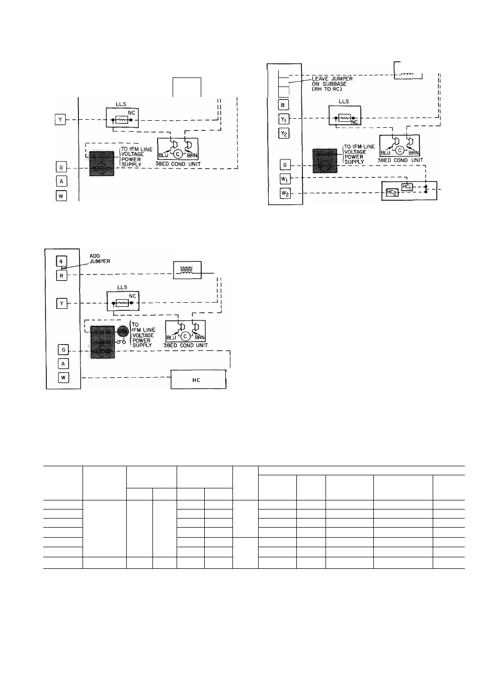
ARRANGEMENT A — COOLING ONLY
THERMOSTAT SUBBASE
HH93AZ042 OR
HH93AZ040
TRANS
-------1
-A J
ARRANGEMENT B — ONE TRANSFORMER,
COOLING AND ONE-STAGE HEATING
THERMOSTAT
SUBBASE
HHAZ93I76
TRANS
MIN 60VA
RH
—
RC
___
ARRANGEMENT C — ONE TRANSFORMER,
COOLING AND TWO-STAGE HEATING
NOTE Refer to unit label wiring diagram for wire colors
IFR, IFM and LLS are located indoors on heating-cooling
applications If accessory IFR is required for cooling-only
applications, locate IFR in fan coil
C
— Contactor
HC
— Heating Control
IFM
— Indoor Fan Motor
IFR
— Indoor Fan Relay
LLS
— Liquid Line Solenoid Valve
NC
— Normally Closed
Trans
— Transformer
Fig. 5 — 24-Volt Control Circuit Connections
Table 4 — Electrical Data (60 Hz)
OPER
VOLTS*
BRANCH CIRCUIT
MODEL
38ED
V/PH
COMPR
FAN
FLA
Min Wire
Sizef
(AWG)
Max
Ft
Wiref
Min Ground
Wire
Size}
Max Fuse or
HACR Type
Ckt Bkr Amps**
MCA
Max
Min
LRA
RLA
018
43 0
7 8
14
32
14
15
10 9
024
54 0
11 5
1 1
12
37
12
25
15 5
030
208-230/1
254
197
65.0
13 7
12
31
12
30
18,2
036
78 8
13 5
12
31
12
30
18.0
042
95 0
19 7
10
34
10
45
26 3
048
116 0
23 7
1 7
8
44
10
50
31 3
060
230/1
254
207
130 0
27 8
8
38
10
60
36.5
AWG
— American Wire Gage
FLA
— Full Load Amps
HACR
— Heating, Air Conditioning and Refrigeration
LRA
— Locked Rotor Amps
MCA
— Minimum Circuit Amps
RLA
— Rated Load Amps
‘Permissible limits of the voltage range at which the unit will
operate satisfactorily
fCopper wire sizes based on 60 C Use copper or copper-clad
aluminum wire only Use latest NEC requirements for copper-
clad aluminum conductor sizing
^Required when using nonmetallic conduit
“Maximum dual element size
NOTE Control circuit is 24 v on all units and requires external
power source