Step 4 — make electrical connections — be, Table 3 — accessories, Step 4 — make electrical connections – Carrier 38ED User Manual
Page 4
Attention! The text in this document has been recognized automatically. To view the original document, you can use the "Original mode".
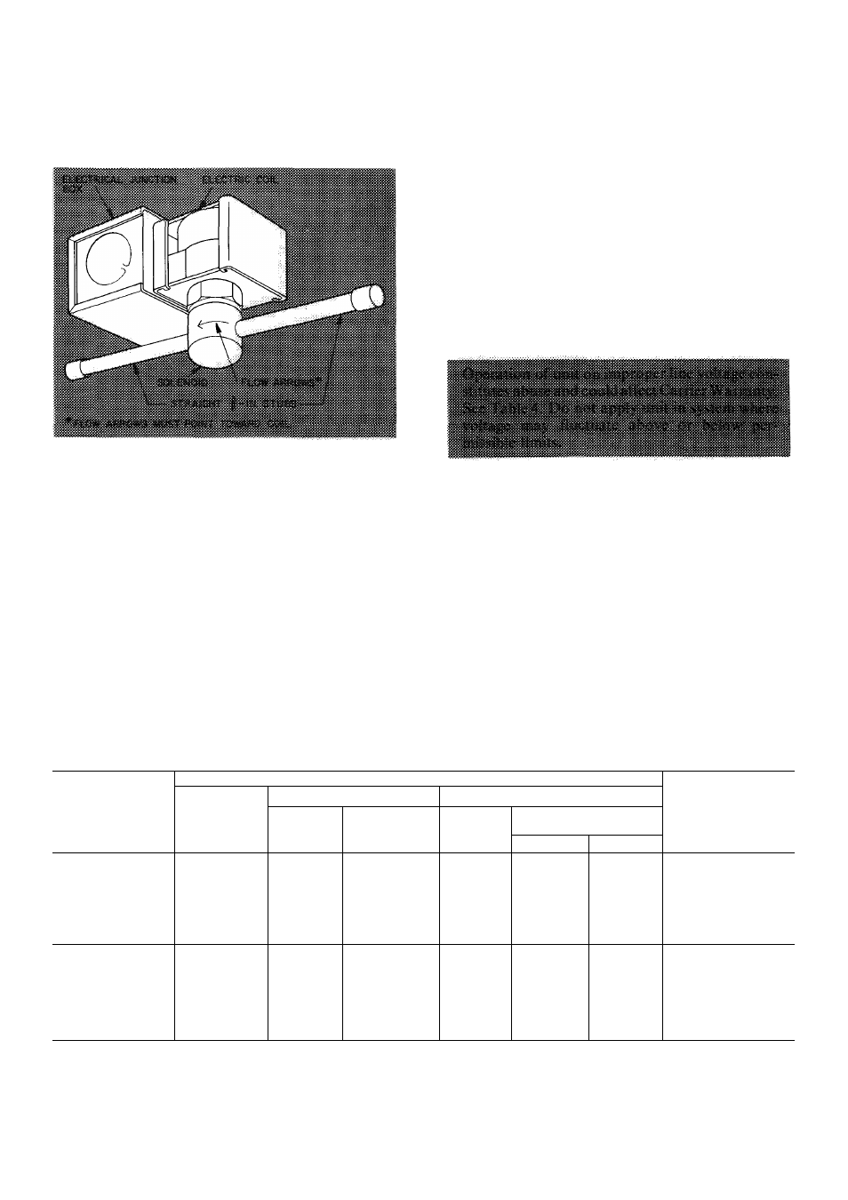
See Fig. 4 and install as follows:
1. Remove coil liquid line cap and discard.
2. Attach field-supplied flare fittings to solenoid
valve straight 3/8-in. stubs.
3.
4.
5.
Connect solenoid to tube assembly, making sure
solenoid flow arrows point towards indoor coil.
Mount solenoid in any position except valve
body at top and electric coil at bottom (see Fig. 4).
Tighten flare nuts.
Wire coil into system control circuit as shown in
Fig. 5.
Step 4 — Make Electrical Connections
— Be
sure field wiring complies with local and national
fire, safety and electrical codes, and that voltage to
unit is within limits shown in Table 4. Contact local
power company for correction of improper line
voltage.
Fig. 4 — Solenoid Installation
Table 3 — Accessories
PART NO.
DESCRIPTION
MODEL 38ED
HH01AD040
HH93AZ040
HH51AR001
Low-Voltage Control — Honeywell Deluxe Thermostat
Thermostat Subbase
Comfort Control Center (Use with HH01AD040)
HH07AT170
HH07AT174
HH93AZ176
Low-Voltage Control — Honeywell Thermostat
Thermostat Subbase (with Automatic Changeover)
HH01AD042
Low-Voltage Control — Honeywell Thermostat
All
HH93AZ042
Thermostat Subbase
38VH90000106
Thermocharger™ Replacement Unit Module (Six 38VH900001)
38GS900102
Indoor Fan Relay (Six HN61KJ210)
HT01AW230
Low-Voltage Transformer (60va) — Available thru Carrier Service Parts
09WQ036.060
Refrigerant-to-water heat exchanger for chilled water systems
38GS900321
Liquid Line Filter Drier (Six 38GS900332)
28VQ9000112
Twelve %
X
IVs-in suction connection adapters
042,048,060
TUBING
PACKAGES
TUBING*
MODEL
38ED
Length
(ft)
Liquid
Suctiont
OD
(in.)
Tube End
OD (in.)
OD
(in.)
Tube End
OD (in.)
Evap
Cond
38LS934151
15
ys
3/8
3/4
3/4
3/4
38LS934201
20
3/8
3/8
3/4
3/4
3/4
38LS934251
25
3/s
3/8
3/4
3/4
3/4
38LS934301
30
3/s
3/8
3/4
3/4
3/4
38LS934351
35
3/8
3/8
3/4
3/4
3/4
38LS934401
40
3/8
ya
3/4
3/4
3/4
38LS934501
50
3/s
ya
3/4
3/4
3/4
38LS978151
15
3/8
3/8
3/8
3/4
3/4
38LS978201
20
3/8
ya
3/8
3/4
3/4
38LS978251
25
3/s
3/8
3/8
3/4
3/4
036,042,
38LS978301
30
3/s
3/8
3/8
3/4
3/4
048,060
38LS978351
35
3/8
3/8
3/8
3/4
3/4
(See Note 2)
38LS978401
40
3/8
3/8
3/8
3/4
3^
38LS978501
50
3/8
3/s
3/8
3/4
3/4
1.,
*For maximum capacities, use suction line sizes recommended in
Table 1 Use of accessory tubing packages smaller than recom
mended may result in slight capacity loss (see Note 2)
fSuction line is insulated and has a 90 degree bend at one end
NOTES;
1
Do not cut ys-in OD liquid line to a length shorter than 10 feet
Do not cut ya-in OD suction lines
Field-supplied IVs-in suction line is recommended on 38ED
036,042,048 and 060 If accessory tubing package is used, a
capacity reduction can result