Service, Fig. 8 — component locations, Service compressor removal – Carrier 38ED User Manual
Page 8
Attention! The text in this document has been recognized automatically. To view the original document, you can use the "Original mode".
actual suction line temperature (step 6) is higher
than table value, the system is undercharged. If
suction line temperature is lower than table
value, system is overcharged.
EXAMPLE: At outdoor air temperature of 85 F
and evaporator temperature of 44 F, the system
will be correctly charged at 60 F ± 2 F suction
line temperature. See Table 7.
Table 7 — 38ED Chargemaster Charging Chart
(AccuRater™ System)
SATURATED EVAPORATOR TEMPERATURE (F)
TEMP
(F)
34
36
38
40
42
■
46
48
50
52
54
56
Suction Line Temperature (F)
60
60
65
49
58
65
70
41
48
58
68
7é;:
75
35
41
48
58
6g;
80
32
36;
42
50
59;
80
71
82
90
61
69
78
95
42
48
53
59
67
79
100
43
47
52
58
68
88
105
44
53
60
75
104
110
49
54
65
80
115
50
62
69
I Example
8 Add charge by slowly opening Chargemaster
valve. If necessary, reduce charge by bleeding at
liquid line service valve. Check outdoor air and
evaporator temperature during procedure. If
they change, refer back to Chargemaster Charg
ing Chart.
Correct use of Chargemaster ensures that an opti
mum refrigerant charge will be in system when con
ditions and system components are normal. How
ever, the Chargemaster does not solve or fix system
abnormalities. It indicates correct charge for condi
tion of the system. It will not make corrections for
dirty filters, slow fans, excessively long or short suc
tion lines or other abnormal conditions. This charg
ing device ensures that a correct relationship exists
between outdoor temperature, evaporator tempera
ture, and suction line temperature on a specific
system.
SIGHT GLASS METHOD — (Field-supplied sight
glass installed in liquid line.) A satisfactory oper
ating charge can be obtained on thermal expansion
valve systems only by charging to a clear sight glass.
For optimum charge, increase high-side pressure to
380 ± 10 psig by blocking condenser fan discharge
or air entering condenser. Charge to a clear sight
glass while holding constant high-side pressure. For
peak efficiency, adjust charge to yield a liquid refrig
erant temperature at the evaporator that is approxi
mately the same as outdoor dry-bulb temperature.
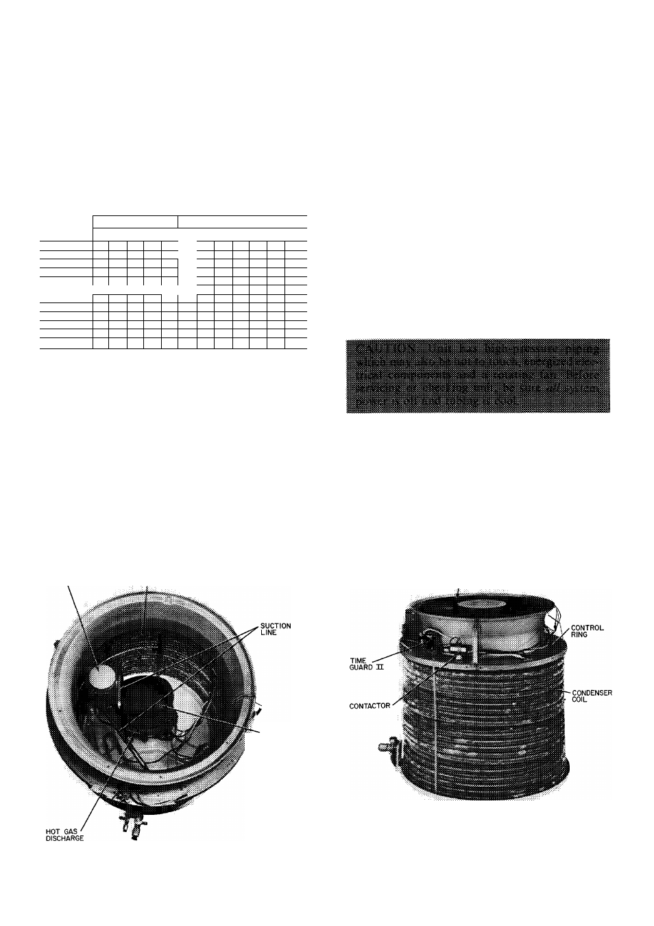
SERVICE
Compressor Removal
— See Table 8 for com
pressor information and Fig. 8 for component loca
tion. Shut off power to unit. Remove refrigerant
from unit using refrigerant removal methods de
scribed in Carrier Standard Service Techniques
Manual, Chapter 1, Refrigerants. Be sure system
pressure is 0 psig before attempting compressor
removal.
ACCUMULATOR
CONDENSER COIL
DISCHARGE GRILLE
(FAN MOTOR UNDERNEATH)
COMPRESSOR
(SOUND SHIELD
REMOVED)
(TOP COVER AND LOUVERED CASING REMOVED)
Fig. 8 — Component Locations
8