A warning, Heat anticipator settings for room thermo – Carrier 38QH User Manual
Page 5
Attention! The text in this document has been recognized automatically. To view the original document, you can use the "Original mode".
HEATING A COOLING
38QH
Heat Pumps — Outdoor Section
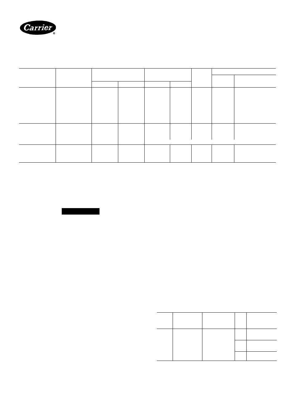
Table 3 — Electrical Data (60 Hz)
3-Phase Available with 030-060 Sizes (SM, DL Option Models)
OUTDOOR
UNIT 38QH
V/PH
OPER VOLTS*
COMPR
FAN
FLA
BRANCH CIRCUIT
MCA
Max Fusef
or HACR Type
Ckt Bkr Amps
Max
Min
LRA
RLA
015301
35
7 1
7
8 6
15
018301
50
8 0
7
12 3
20
024301
54
12 9
9
15 3
25
030301
78
14 5
9
20 3
35
036301
208/230/1
254
187
86 7
14 9
9
21 3
35
042301
107 4
18.3
1 9
27 3
45
048301
110
20 4
1 9
29 9
50
060331
130
25 9
1 9
34 3
60
060341
142
31 2
1 9
40 9
60
030501
59.5
10 6
.9
15 4
25
036501
65
11.5
.9
16 5
25
042501
208-230/ЗФ
245
187
74
133
9
19 1
30
048501
92
147
1 9
20 9
35
060531
Not Available
036601
042601
048601
060631
460/Зф
506
414
32 8
37
46
5 1
62
70
1 1
1.3
1 3
Not Ava
7.5
9 1
10.1
liable
15
15
15
FLA
— Full Load Amps
HACR
— Heating, Air Conditioning, Refrigeration
LRA
— Locked Rotor Amps
MCA
— Minimum Circuit Amps
RLA
— Rated Load Amps
'Permissible limits of the voltage rangeât which unitwill operate satisfactorily
fTime-delay fuse.
|3-Phase available only with Deluxe and SM option units.
NOTE: Control circuit is 24 v on all units and requires external power source.
A
WARNING
To avoid personal injury, be sure indoor blower has
stopped before attempting service or maintenance.
pump shutdown. When one outdoor thermostat is used,
a supplemental heat relay is not required. The supple
mental heat switch in the indoor thermostat subbase
bypasses outdoor thermostat, locks out compressor and
activates electric heater.
Heat Anticipator Settings for Room Thermo-
Stat(HH01AT171) — Set anticipator for room thermo
stat according to Table 4. These settings may be changed
slightly to provide a greater degree of comfort for a par
ticular installation.
MOUNT OUTDOOR THERMOSTAT in control box.
Attach brackets with short sheet metal screws to avoid
contact with coil. Leave capillary tube coiled in control
compartment making sure it is clear of all electrical con
nections and sharp metal edges.
Accessory Outdoor Thermostat provides adjust
able outdoor control of accessory electric heater. This
thermostat makes contact when a drop in outdoor tem
perature occurs. It energizes a stage of electric heat
when the outdoor temperature setting is reached, pro
vided the room thermostat is on the second stage of heat
ing. One outdoor thermostat is recommended for each
stage of electric heat after the first stage. Set the outdoor
thermostat(s) progressively lower for each stage. Refer
to heat load of building and unit capacity to determine
the correct outdoor thermostat settings.
The accessory supplemental heat relay is required when
2 outdoor thermostats are used. It is automatically ener
gized by the manually operated supplemental heat switch
in the indoor thermostat subbase. The thermostat locks
out compressor and the relay bypasses the outdoor
thermostats for electric heater operation during heat
MOUNT SUPPLEMENTAL HEAT RELAY in con
venient location on indoor unit. Attach with sheet metal
screw.
Table 4 — Thermostat Anticipator Settings
UNIT
38QH
FIRST-
STAGE
ANTICIPATOR
SETTING
INDOOR
UNIT WITH
ELECTRIC
HEATER
HTR
kW
SECOND-
STAGE
ANTICIPATOR
SETTINGS
015
018
024
030
036
042
048
060
Fixed
40DQ and
40AQ Fan Coil
with 40AQ FItrs
or 40QB Fan Coil
with 40QB Htrs
50
7 5
10.0
25
15 0
20 0
25.0
50
30 0
34.0
75
Manufacturer reserves the right to discontinue, or change at any time, specifications or designs without notice and without incurring obligations.
Booklll4
PC101
Catalog No 533-808
PrintedinUSA
Form38QH-2SI
Pg 5
7-85
Replaces: 38QH-1 SI
For replacement Items use Carrier Specified Parts
Tab I5al5a