A caution, Compatible fitting repair – Carrier 38QH User Manual
Page 2
Attention! The text in this document has been recognized automatically. To view the original document, you can use the "Original mode".
HEATING & COOLING
38QH
Heat Pumps.^^utdoor Section
Table 1 — Physical Data
MODEL 38QH
015
018 024 030 036 042 048
060
OPER WT (lb)*
132
145
180
195
195
235
235
270
REFRIGERANT
Control
COND FAN
Air Discharge
AirQty (Cfm)
Mtr Rpm (60 Hz)
COND COIL (FIn/in.)
Tube Diam
Rows
Refrig Ckts
Face Area (sq ft)
Outer Row
Inner Row
DIMENSIONS (ft-in.)
Diameter
Height
CONNECTIONS (in. ODF)
Suction
Liquid_________________
REFRIG LINES (in. ODF)
Suction
Liquid________________
22
AccuRater” (Bypass Type)
Propeller Type, Direct Drive
Vertical
1850 I 3100 I 4000
15000
830
850
840
17.11
2188
17.11
21.88
3-2'/2
Compatible Fitting (Suction)
& Flare (Liquid)
1
y4
%
I'/at
*Add 10 lbs for louvered casing (if so equipped). Weight increases slightly
with addition of any accessories
t38QFI042-060 require 1’/e-in. suction line for optimum performance. A
%- X I'/a-in connection adapter accessory (Carrier Part No 28AU900061)
is available. If a 7e-ln accessory tubing package is used, expect a 2'/2%
capacity loss
A
CAUTION
DO NOT BURY MORE THAN 3 FT OF REFRIG
ERANT TUBING IN GROUND. If any section of
tubing is buried, there must be a 6-in. vertical rise to
valve connections on outdoor unit. If more than the
recommended length is buried, refrigerant may
migrate to cooler buried section during extended
periods of unit shutdown. This causes refrigerant
slugging and possibly compressor damage at start-up.
CONNECT REFRIGERANT LINES to fittings on out
door unit suction and liquid service valves (Fig. 1). Unit
Compatible Fittings permit mechanical (quick-connect)
or sweat connections.
Models 38OH042,048,060 — When using 1 -1 /8 in. field-
supplied refrigerant suction line, sweat-connect suction
line to 1-1/8 in. end of required connection adapter. Be
sure to provide a heat sink at the service valve to prevent
damage during sweating operation. Connect 3/4-in. end
of adapter to unit suction line Compatible Fitting.
Connect liquid refrigerant line to unit. When a 7/8-in.
field-supplied suction line is used, provide a field-supplied
3/4-in. to 7/8-in. suction line adapter (not necessary if
38LS accessory tubing is used).
Mechanical Connection — Mate one set of connections at
a time.
1. Loosen nut on Compatible Fitting one turn. Do not
remove.
2. Remove plug and be sure O-ring is in the groove inside
the Compatible Fitting.
3. Cut tubing to correct length. Deburr and size as
necessary.
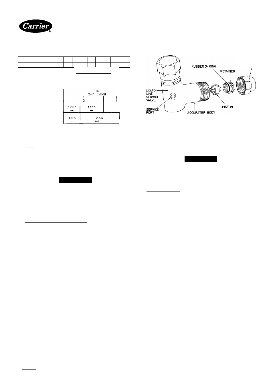
FLARE NUT
Fig. 2 — AccuRater (Bypass Type) Components
4. Insert tube into Compatible Fitting until it bottoms.
Tighten nut until it bottoms on shoulder of fitting or
valve. Keep tube bottomed in Compatible Fitting
while tightening nut.
A
CAUTION
If undersized, damaged or elliptically-shaped
tubing is used when making Compatible Fitting,
leaks may result.
Sweat Connection— Use refrigerant grade tubing.
1. Remove locking nut, rubber O-ring and Schrader core
and cap from valve service port.
2. Cut tubing to correct length. Deburr and size as
necessary.
3. Insert tube in Compatible Fitting until it bottoms.
NOTE: Wrap top and bottom of service valves in wet
cloth to prevent damage by heat. Solder with low-
temperature 430 F silver alloy solder.
4. Replace Schrader core and cap.
5. Evacuate or purge system with field-supplied
refrigerant.
Compatible Fitting Repair
MECHANICAL CONNECTION — Frontseat unit
service valves. Relieve refrigerant pressure from tubing.
Back off locknut from Compatible Fitting onto tube. Cut
fitting between threads and O-ring. See Fig. 3. Remove
tubing section remaining in threaded portion of fitting.
Discard locknut.
Clean, flux and insert new tube end into remaining
portion of Compatible Fitting. Wrap valve in wet rag to
prevent damaging factory-made joints. Heat and apply
low-temperature (430 F) solder.
SWEAT CONNECTION — Frontseat unit service
valves. Relieve refrigerant pressure from tubing. Clean
and flux around leak. Repair, using low-temperature
(430 F) solder. Evacuate or purge evaporator coil and
tubing system. Add refrigerant charge. Refer to Table 5.
©
Manufacturer reserves the right to discontinue, or change at any time, specifications or designs without notice and without incurring obligations.
Book| 1 |4
PC101
Catalog No 533-808
PrintedinUSA
Form38QH-2SI
Pg 2
7-85
Replaces: 38QH-1 SI
X aK IAaIRa
For r<»nlacement items use Carrier Soecified Parts