Step 4 — make electrical connections — be, Table 2 — accurater™ selection charts, Fig. 3 — compatible fitting – Carrier 38QH User Manual
Page 3: Fig. 4 — line power connections
Attention! The text in this document has been recognized automatically. To view the original document, you can use the "Original mode".
HEATING A COOLING
38QH
Heat Pumps — Outdoor Section
Table 2 — AccuRater™ Selection Charts
OUTDOOR
INDOOR
INDOOR
OUTDOOR
INDOOR
INDOOR
UNIT 38QH
UNIT
PISTON
UNIT 38Qh
UNIT
PISTON
28AC015
49‘
28AC.AU042
80*
28AC.AU018
49’
28AC242
80*
28HQ.VQ024
49*
28AC.AU048
82*
015
40AQ018
46
28AC248
82*
(35)t
40AQ024
49*
28AM048
82
40DQ014
46*
842
(73)t
28HQ.VQ042
76
40DQ018
46*
28HQ.VQ048
80*
40DQ024
49
28HQ.VQ060
28SL042
82*
76*
28AC.AU018
52*
28AC.
au
,AM024
28HQ.VQ024
55*
52*
28SL060
82*
018
(42)t
28HQ.VQ030
40AQ018
40AQ024
55*
49*
52
40QB.QH048
82
28AC.AU048
84
40AQ030
55*
28AC248
84
40DQ018
49*
28AC.AU060
86*
40DQ024
52*
28AC260
86*
40DQ030
55*
28AM048
84*
024
(52)t
28AC,AU,AM024
28AC.AU030
28AM036
28HQ.VQ024
28HQ.VQ030
28HQ.VQ036
40AQ024
40AQ030
61*
63*
63*
59*
61*
63*
59*
61’
048
(73)t
28HQ.VQ048
28HQ.VQ060
28SL048
28SL060
40QB048
40QB.QH060
40QB.QH062
82*
84*
82
84*
84*
86*
86*
28AC.AU060
101*
40AQ036
63*
28AC260
101*
40DQ024
59
060331
28HQ.VQ060
98*
40DQ030
61*
(78)t
28SL060
98*
28AC.AU030
28AC.AU036
28AC236
70*
73
40QB,QH060
40QB.QH062
101*
101*
73
28AC.AU060
93*
28AM036
70*
28AC260
93*
28HQ.VQ030
67*
060341
28HQ.VQ060
90*
030
(59)t
28HQ.VQ036
70*
(78)t
28SL060
90*
28HQ.VQ042
73*
40QB.QH060
93
28SL030
28SL036
67*
70*
40QB.QH062
93
28SL042
73*
40AQ030
67*
40AQ036
70*
40DQ030
67*
28AC.AU036
73
28AC236
73
28AC.AU042
73’
28AC242
73*
28AM036
70*
036
(61 )t
28HQ.VQ036
70*
28HQ.VQ042
73*
28HQ.VQ048
73*
28SL036
70*
28SL042
73*
28SL048
73*
40AQ036
70*
40QB042
73’
'Replace factory-installed piston with this piston size
fRequired outdoor piston size
Step 4 — Make Electrical Connections — Be
sure field wiring complies with local and national fire,
safety and electrical codes, and voltage to system is within
limits shown in Table 3. Contact local power company
for correction of improper line voltage.
NOTE: Operation of unit on improper line voltage con
stitutes abuse and could affect Carrier warranty. See
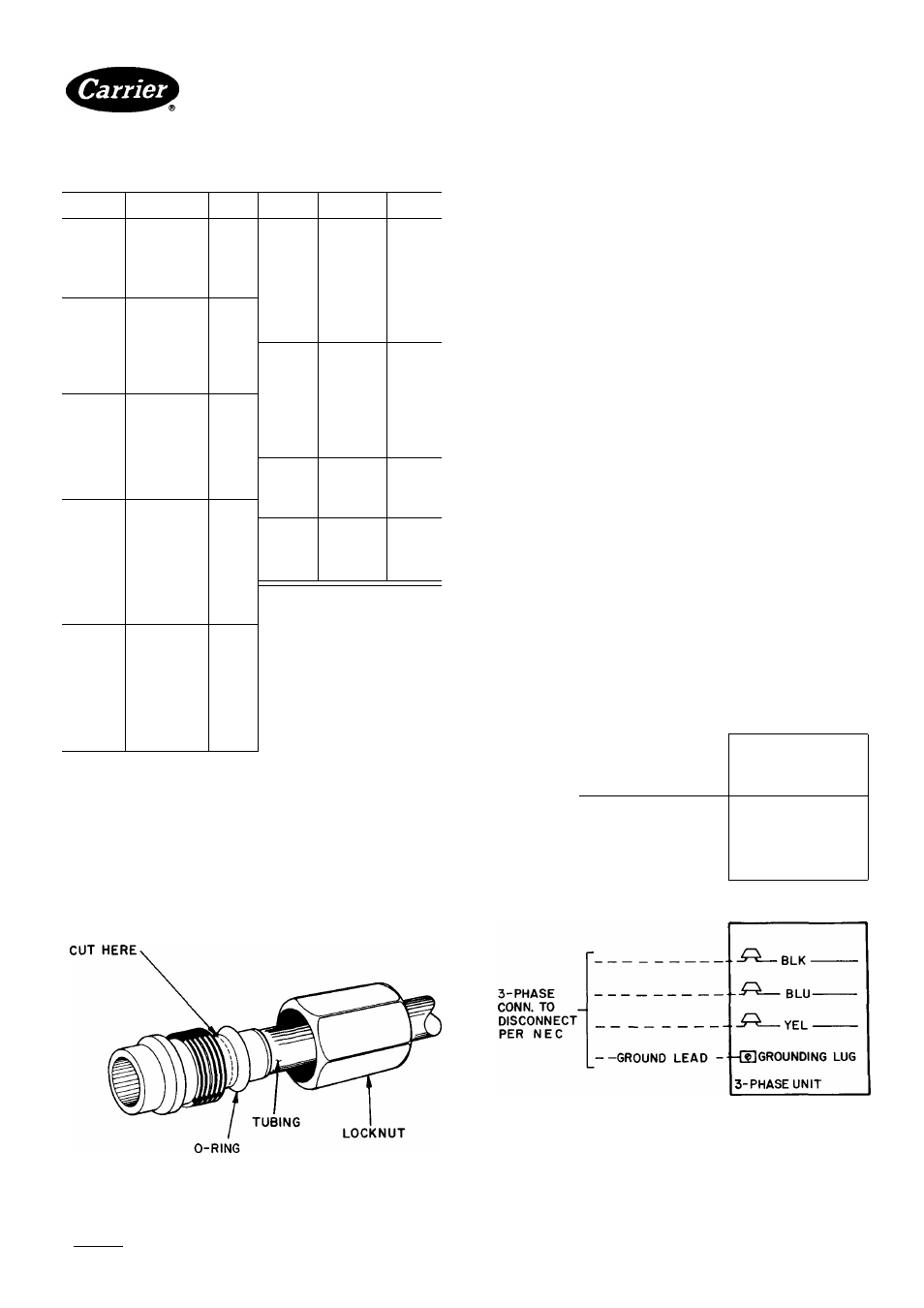
COMPATIBLE FITTING
Table 3. Do not install unit in system where voltage may
fluctuate above or below permissible limits.
See Table 3 for recommended fuse sizes. When making
electrical connections, provide clearance at unit for refrig
erant piping connections.
INSTALL BRANCH CIRCUIT DISCONNECT PER
NEC of adequate size to handle unit starting current.
Locate disconnect within sight from and readily access
ible from unit, per Section 440-14 of National Electrical
Code (NEC).
ROUTE LINE POWER LEADS — Extend leads from
disconnect through power wiring hole provided (see
Fig. 1) and into unit splice area. Remove control box
cover to gain access to unit wiring.
CONNECT GROUND LEAD AND POWER WIRING
— Connect ground lead to ground connection in control
box for safety. Then connect power wiring. See Fig. 4.
Splice line power leads to yellow and black pigtails. Use
wire nuts and tape at each connection. Connect unit
wiring to copper power wiring only.
CONNECT CONTROL POWER WIRING — Route
24-v control wires through control wiring hole and
channel and eonnect leads to control wiring terminal
board. See Fig. 1 and 5.
Use furnace or fan coil transformer as 24-v (40-va
minimum) supply for system as shown in Fig. 5, or use
accessory transformer (refer to Service data).
I-PHASE
CONN. TO
DISCONNECT
PER NEC
-------- GROUND LEAD-
-IU
grounding
lug
_----------------------------------
— YEL
1- PHASE
UNIT
Fig. 3 — Compatible Fitting
^
Splice Connections
_________ Field Wiring
---------------- Factory Wiring
Fig. 4 — Line Power Connections
Manufacturer reserves the right to discontinue, or change at any time, specifications or designs without notice and without incurring obiigations.
Book|1 14
PC101
Catalog No 533-808
Printed in U.S A
Form38QH-2SI
Pg 3
7-85
Replaces: 38QH-1 SI
Fnr ronlnrAmAnl Home tieo f^orrior fino/^ilioH Dorte
Tah IRaIRa