Electrical data, Cautions – Carrier 51CV/GY User Manual
Page 4
Attention! The text in this document has been recognized automatically. To view the original document, you can use the "Original mode".
ELECTRICAL DATA...
A)
All wiring must comply with local and national elec
trical codes. All wiring must be installed by qualified
and skilled electricians. If you have any questions
regarding the following instructions, contact a qualified
electrician.
B)
Check available power supply and resolve any
household wiring problems BEFORE installing and
operating this unit.
C)
An individual branch circuit and single wall recepta
cle used only for this appliance, is required. See Table
1 for suggested wire sizes for individual branch circuit.
D)
For your safety and protection, this unit is grounded
through the service cord plug when plugged into a
matching wall outlet.
If you have any question
whether your wall outlet is grounded or not please
consult a qualified electrician.
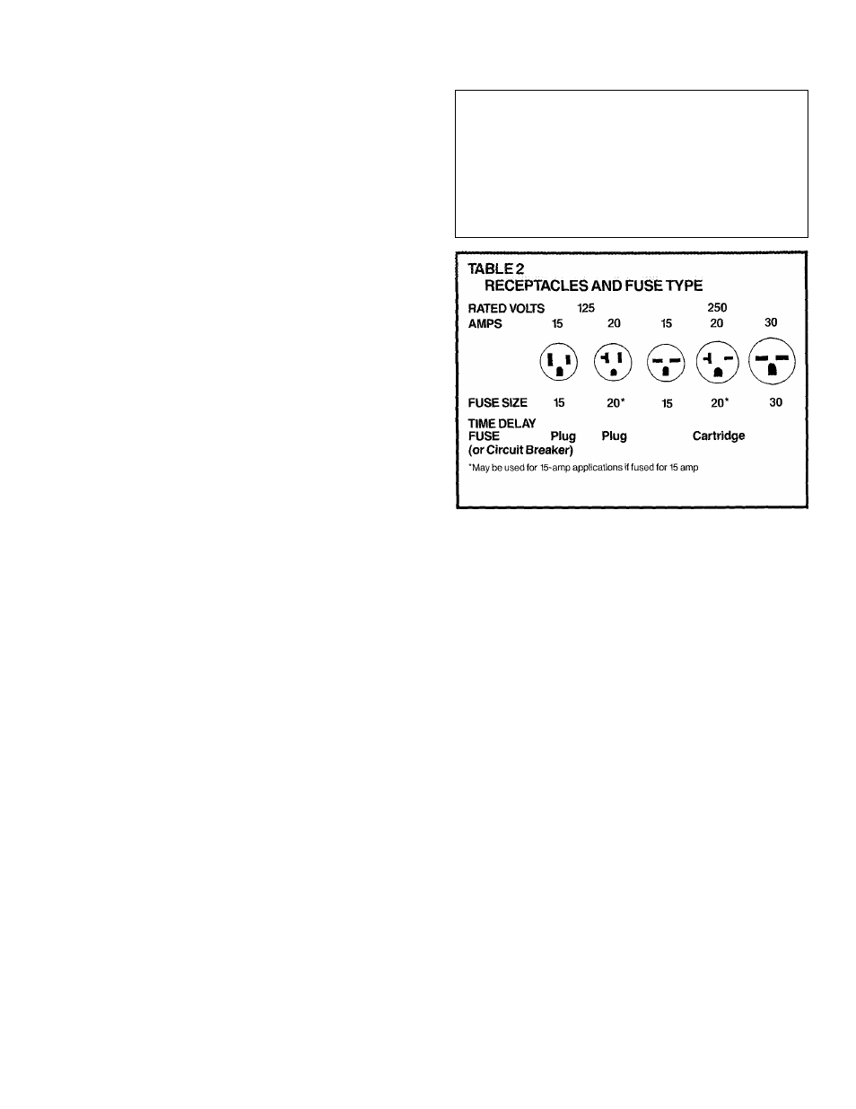
E)
The wall outlet you select must match the plug on
the unit’s service cord and must be within reach of the
installed unit.
Do NOT use adaptors or extension
cords. See Table 2 for further receptacle and fuse
information.
F)
Follow fuse specifications indicated on unit’s name
plate. See Table 2. Nameplate is located above unit’s
control panel (refer to diagram in Step 7 of Window
Installation Steps).
NOTE:
Unit’s model and serial
numbers can be found on the nameplate. Record
numbers on the front of this manual for future
reference.
TABLE 1
SUGGESTED INDIVIDUAL BRANCH CIRCUIT
NAMEPLATE AMPS
AWG WIRE SIZE*
5.0 to 12
14
12.1 to 16
12
16.1 to 24
10
AWG—
American Wire Gauge
'Based on copper wire at 60°C temperature rating
CAUTIONS:
Manufacturer strongly recommends using two people
during installation of units.
Coil fins on chassis are sharp and chassis is heavy.
Please keep this manual handy for future reference.
Please note:
In the summer; condensation (water)
run-off out the unit’s back is normal during cooling
operation under high humidity weather conditions. In
the winter; the unit is designed with a drain located in
the basepan to open at approximately SOT to minimize
formation of ice in the basepan during heating opera
tion. Unit should be installed where condensation
run-off will not drip on pedestrians or neighboring
properties. In addition it may be necessary to re-direct
drainage flow in the winter to prevent possible build-up
of ice on pedestrian walkways. To re-direct drainage
flow, an Accessory External Drain Kit is available.
Contact your independent Carrier Dealer or call
T800-CARRIER for information.