Carrier 51CV/GY User Manual
Page 11
Attention! The text in this document has been recognized automatically. To view the original document, you can use the "Original mode".
Measure center of window on sash and sill.
I^Make a small pencil mark to indicate spot. Raise
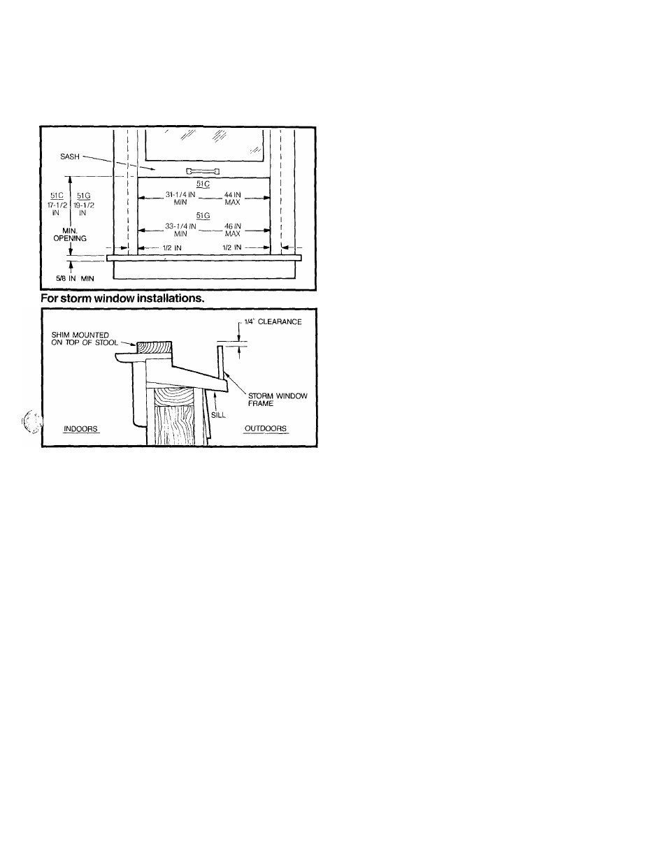
sash. Position bottom track on sill lining up with
center mark.*3
If storm windows present interference, fasten a
2" wide wood strip to window’s sill. Thickness of
wood strip should equal height of storm window’s
ledge. By inserting wood strip, you will create a level
surface for unit installation.
I
Screw track onto sill using 3
short
screws.
I
Slide wing panels from unit mounting kit into
kit’s upper guide, with drain holes on bottom of wing
panels facing outward for condensation run-off.
I
Slip lower portion of connected wing panels
into bottom track now on sill.
I
Stretch wing panels out on both sides to meet
window frame.
Lower window sash onto upper guide.
I
With sash firmly down upon upper guide,
make a pencil mark on lowered window sash
through center hole on upper guide.
I
Drill hole at mark and insert provided
short
screw. DO NOT completely tighten screw.
I
Move accordion fold? aside to reveal holes on
sides of wing panels. Use previous marking tech
nique (Step 11) and drill holes in pencil marked
spots. Secure wing panels in sash tracks by insert
ing
long
screws in drilled holes and tightening.
Make pencil marks through all holes in bottom
track while track is positioned on window sill.
I
Remove track and drill three holes in window
sill at marked spots.
I
Remove paper backing from narrow seal strip
in unit accessory mounting kit and fasten strip to top
of casing, aligning with pre-drilled holes in casing.
Fasten top channel to top of casing using 4 screws,
inserted upwards from inside casing.
*3
If your window width exceeds our maximum recommen
dation, then your unit will require additional support.