Fig. 8 — timer sequence chart – Carrier 38AE User Manual
Page 7
Attention! The text in this document has been recognized automatically. To view the original document, you can use the "Original mode".
Head Pressure Control
by means of/an
cycling is a
standard feature of 38AE012-016 units. The no. 2 fan cy
cles in response to changes in liquid pressure. The switch
cycles the fan off at 126 ± 4 psig (869 ± 28 kPa) as pres
sure decreases, and cycles back on at 257 (-1-5, -0) psig
(1772 [-f 103, -0] kPa).
CONTROL
SET POINT
ADJUSTMENT
NUT
PRESSURE
DIFFERENTIAL
ADJUSTMENT
SCREW
VALVE BODY
BYRASS
PISTON
DIFFERENTIAL SCREW'
SEALING CAP
(CAP MUST BE REPLACED
TO PREVENT REFRIGERANT LEAKAGE)
Fig. 7 — Compressor Capacity Controi Unloader
Time Guard® II Circuit
provides for a delay of ap
proximately 5 minutes before restarting compressor after shut
down from safety device action.
On start-up, the Time Guard II timer causes a delay of
approximately 3 seconds after thermostat closes.
On compressor shutdown, the timer recycles for approx
imately 5 minutes. During this time, the compressor cannot
restart.
Refer to Fig. 8 and to label diagram on unit.
TIME DELAY TIMING SEQUENCE
T1-T2
---------- RUNNING TIME---------- »■
p«------ 3SEC ------------------------- »■
5 MIN
wimmmmmmimiri.
WIA
DENOTES CLC6ED CONTACTS
Fig. 8 — Timer Sequence Chart
Winter-Start Control (If Required)
- install Ac
cessory Package 38AE900021.
Crankcase Heater
prevents refrigerant migration and
compressor oil dilution during shutdown whenever com
pressor is not operating. It is wired into the control circuit,
cycling with the compressor, off when compressor is run
ning, and on when compressor cycles off.
Both compressor service valves must be closed when
ever crankcase heater is deenergized for more than 6 hours.
The crankcase heater is operable as long as the control cir
cuit is energized.
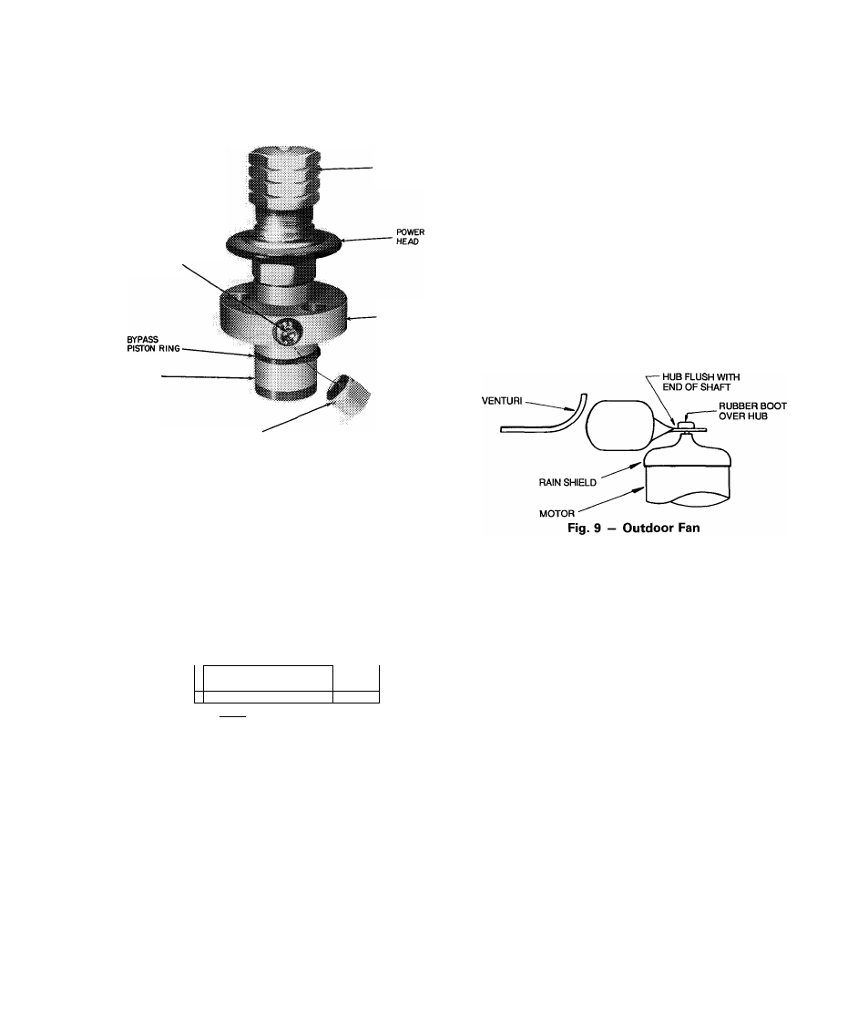
Outdoor Fans
— Each fan is supported by a formed-
wire mount bolted to the fan deck and covered with a wire
guard. The exposed end of the motor shaft is covered with
a rubber boot. In case a fan motor must be repaired or re
placed, be sure the rubber boot is put back on when the fan
is reinstalled and be sure the fan guard is in place before
starting the unit. Figure 9 shows the proper position of the
mounted fan. Fan motors have permanently lubricated
bearings.
Lubrication
FAN MOTORS have sealed lubrication bearings. No pro
visions for lubrication are made.
COMPRESSOR has its own oil supply. Loss of oil due to a
leak in the system should be the only reason for adding oil
after the system has been in operation. See Oil Charge
section.