Carrier 38AE User Manual
Page 6
Attention! The text in this document has been recognized automatically. To view the original document, you can use the "Original mode".
Preliminary Charge
— Refer to Carrier Standard Serv
ice Techniques Manual, Chapter 1, Section 1-8. By the liq
uid charging method and charging by weight procedure, charge
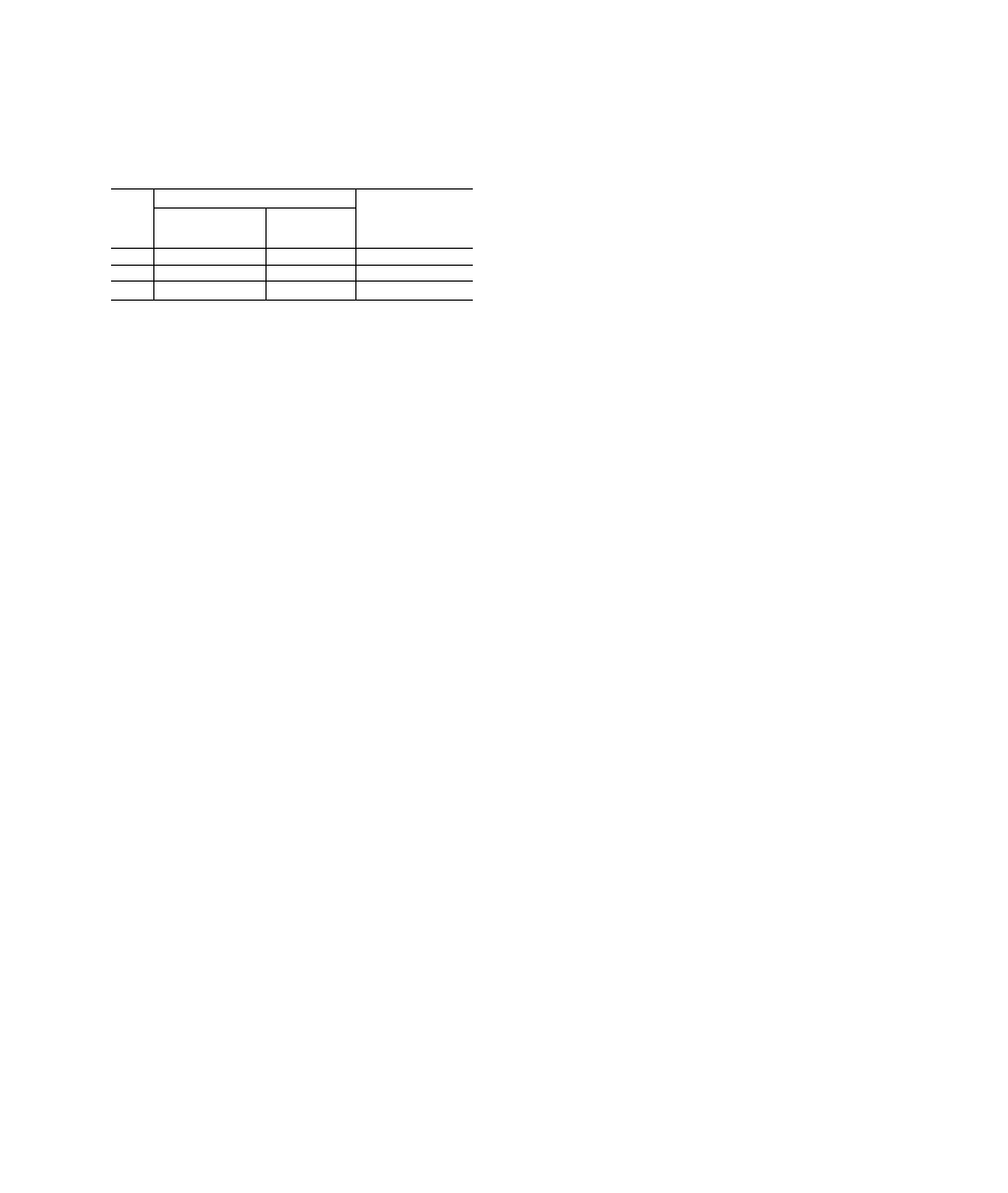
the units with approximately the following amounts of R-
22: 38AE012, 22 lb (10 kg); 38AE014, 23 lb (10.5 kg);
38AE016, 23 lb (10.5 kg). See Table 5.
Table 5 — Charging Data (R-22)
UNIT
38AE
REFRIGERANT CHARGE - lb (kg) CONDENSING
TEMP
DURING
CHARGING - F (C)
Required Charge
Above Clear
Sight Glass
Outdoor Unit
Total Charge
(Approx)
012
3.0 (1.4)
22 (10)
125 (51.7)
014
4.8 (2.2)
23 (10.5)
123 (50.6)
016
3 4 (1 5)
23 (10.5)
130 (54.4)
Start the Unit
— The field disconnect is closed, the
fan circuit breaker is closed, and the space thermostat is set
above ambient temperature so that there is no demand for
cooling. Only the crankcase heaters are energized. After
the heaters have been on for 24 hours, the unit can be started.
Close the compressor circuit breakers, and then reset the
space thermostat
below
ambient temperature, so that a call
for cooling is ensured.
Energize Branch Circuit
— Set room thermostat above
ambient temperature.
Close field disconnect switch. Be sure
that compressor crankcase heaters are operating. Allow crank
case heaters to operate a minimum of 24 hours before start
ing unit.
To Start Unit
set room thermostat below ambient.
Af
ter starting unit, there will be a delay of at least 3 seconds
before compressor starts.
Oil Charge
(see Table 1) —Allow unit to run for about
20 minutes. Stop unit and check compressor oil level. Add
oil only if necessary to bring oil into view in sight glass.
Use only Carrier-approved compressor oil.
Approved oils
are:
Witco Chemical Corp.............................................Suniso 3GS
Texaco, Inc..................................................................... WF32
Petroleum Specialties Co.........................................Cryol 150
Do not reuse drained oil or use any oil that has been ex
posed to atmosphere.
Procedures for adding or removing
oil are given in Carrier Standard Service Techniques Man
ual, Chapter 1, Refrigerants.
If oil is added, run unit for additional 10 minutes. Stop
unit and check oil level. If level is still low, add oil
only
after
determining that piping system is designed for proper
oil return and that the system is not leaking oil.
Check Operation
of all safety controls. Replace all
service panels.
Be sure that control panel cover is closed
tightly.
OPERATING SEQUENCE
Cooling
— When the first stage (TCI) of the cooling
thermostat closes, the timer starts. After approximately 3
seconds, the timer activates the compressor and fan motor
no. 1 contactor. When the liquid pressure builds to approx
imately 257 psig (1772 kPa), fan motor no. 2 is energized.
On demand for additional cooling capacity, the second
stage (TC2) of the cooling thermostat closes, energizing a
field-supplied liquid line solenoid valve (LLS) which opens.
This increases the suction pressure, causing the compressor
to operate at higher capacity.
When fan switch is set at AUTO., the indoor-air fan cy
cles with the compressor. When the switch is set at CONT,
the indoor-air fan runs continuously.
At shutdown, the Time Guard® II timer prevents the com
pressor from restarting for approximately 5 minutes.
In addition, a field-supplied solenoid valve wired in par
allel with the compressor contactor coil, shuts off the liquid
line to prevent refrigerant migration back to the compressor
during the off cycle.
Heating
— The heating thermostat (TH) energizes a field-
supplied relay which operates heating controls and ener
gizes the indoor-fan relay. When the fan switch is set at
AUTO., the indoor-air fan cycles with the heating control.
The indoor-air fan runs continuously when the fan switch is
set at CONT.
Fan Cycling
is employed for head pressure control. The
no. 2 fan responds to liquid line pressure, cycling on at ap
proximately 257 psig (1772 kPa) and off at approximately
126 psig (869 kPa).
Winter Start Control (If Required)
— install Ac
cessory Package 38AE900021.
SERVICE
Capacity Control
— A suction pressure-actuated un
loader controls 2 cylinders and provides capacity control.
Unloaders are factory set (see Table 1), but may be field
adjusted:
CONTROL SET POINT (cylinder load point) is adjustable
from 0 to 85 psig (586 kPa). To adjust, turn control set
point adjustment nut (Fig. 7) clockwise to its bottom stop.
In this position, set point is 85 psig (586 kPa). Then, turn
adjustment counterclockwise to desired control set point.
Every full turn counterclockwise decreases set point by 7.5
psig (51.7 kPa).
PRESSURE DIFFERENTIAL (difference between cylinder
load and unload points) is adjustable from 6 to 22 psig (41.4
to 152 kPa). To adjust, turn pressure differential adjust
ment screw (Fig. 7) counterclockwise to its back stop po
sition. In this position, differential is 6 psig (41.4 kPa).
Then, turn adjustment clockwise to desired pressure differ
ential. Every full turn clockwise increases differential by
1.5 psig (10.3 kPa).