Start-up evacuate and dehydrate, Leak test, Before starting unit – Carrier 38AE User Manual
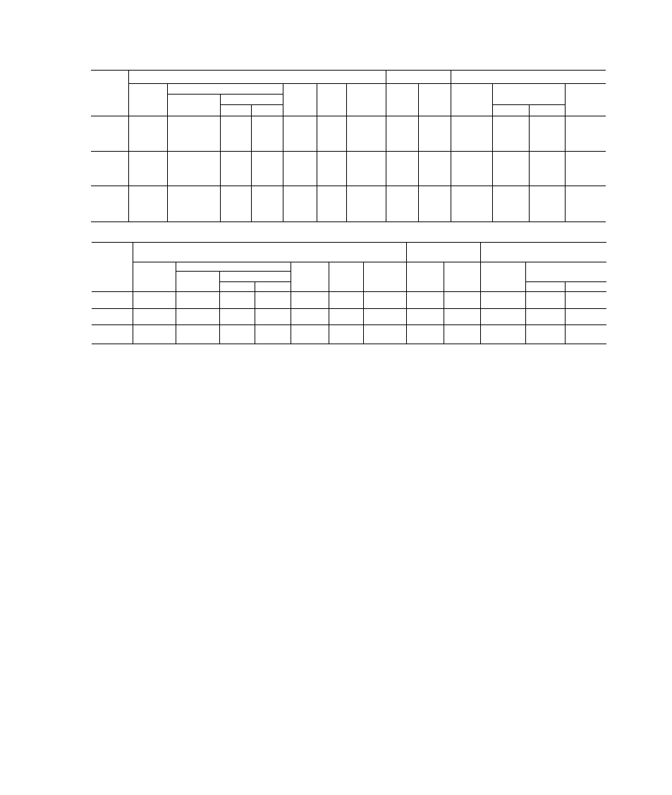
Page 5: Table 4 - electrical data
Attention! The text in this document has been recognized automatically. To view the original document, you can use the "Original mode".
(3 Ph/60 Hz)
Table 4 - Electrical Data
UNIT
38AE
UNIT
COMPR
FAN MOTORS (Single Phase)
Model
Volts
MCA
ICF
MOCP
(Fuse)
RLA
LRA
Total
Fans
FLA (ea)
Fan No.
kW
Nameplate
Supplied*
Min
Max
1
2
501
208-230
187
253
62.5
178
100
43 6
170
4.3
37
012
201
380
342
418
35.0
101
50
24 0
93
4.3
37
601
460
414
528
29 1
81
40
20.0
77
23
1 9
101
575
518
660
22.8
67
35
157
62
1.8
1.8
501
208-230
187
253
69.3
199
100
49 3
191
43
37
201
380
342
418
38 0
112
60
26 5
104
43
37
601
460
414
528
31 7
84
50
22 1
80
23
1 9
101
575
518
660
25.6
73
40
17.9
69
1.8
1.8
501
208-230
187
253
87 5
274
125
63 6
266
43
37
201
380
342
418
49 3
153
80
36.0
145
43
37
601
460
414
528
40 7
124
60
29 3
120
2.3
1 9
101
575
518
660
33 0
100
50
23 8
96
1.8
1 8
(3 Ph/50 Hz)
UNIT
38AE
UNIT
COMPR
FAN MOTORS
230 V (Single Phase)
Model
Volts
MCA
ICF
MOCP
(Fuse)
RLA
LRA
Total
Fans
FLA (ea)
Fan No.
Name-
plate
Supplied*
Min
Max
1
2
803
230
198
264
47 5
134
75
32 9
128
29
35
903
400
342
457
31 4
80
50
20.0
74
2.9
3.5
803
230
198
264
51 0
149
75
35 7
143
29
3.5
903
400
342
457
34 0
89
50
22 1
83
29
3.5
803
230
198
264
66 9
206
100
47 9
200
2.9
35
903
400
342
457
43 0
121
60
29 3
115
29
35
FLA —
Full Load Amps (Fan Motors)
ICF —
Maximum Instantaneous Current Flow during start-up (LRA of compressor plus total FLA of fan motors)
kW —
Total Fan Motor Input (kilowatts)
LRA —
Looked Rotor Amps
MCA —
Minimum Circuit Amps per NEC (U S.A ), Section 430-24
MOCP —
Maximum Overcurrent Protection (amps)
RLA —
Rated Load Amps (Compressor)
•Units are suitable for use on electrical systems where voltage supplied to the unit terminals is not below or above
the listed limits
START-UP
Evacuate and Dehydrate
the entire refrigerant sys
tem by either of the methods described in Carrier Standard
Service Techniques Manual, Chapter 1, Section 1-7.
Leak Test
the entire refrigerant system by the pressure
method described in Carrier Standard Service Techniques
Manual, Chapter 1, Section 1-6. Use R-22 at approxi
mately 25 psig (172.4 kPa) backed up with an inert gas to
a total pressme not to exceed 245 psig (1689 kPa).
Before starting the unit, the crankcase heaters must be
on for 24 hours to be sure all the refrigerant is out of the
oil.
To energize the crankcase heaters, proceed as follows.
1. Set the space thermostat above ambient so there will be
no demand for cooling.
2. Close the field disconnect.
3. Turn the fan circuit breaker on. Leave the compressor
circuit breakers off. The crankcase heaters are now
energized.
Before Starting Unit
check the following:
1. Compressor oil level must be at least within sight in the
compressor sight glass. Add oil if necessary (see Table
1 and Oil Charge section).
2. Compressor holddown bolts must be snug, but not tight.
Refer to Compressor Mounting section and tag on com
pressor foot.
3. All internal wiring connections must be tight; all barri
ers and covers must be in place.
4. Electrical power source must agree with unit nameplate
rating.
5. All service valves must be open.
6. Crankcase heater must be firmly locked into the com
pressor crankcase.