Table 1 — physical datrf, Fig. 2 — component locations – Carrier 38AE User Manual
Page 2
Attention! The text in this document has been recognized automatically. To view the original document, you can use the "Original mode".
ENGLISH
Table 1 — Physical Datrf^
UNIT 38AE
012
014
016
OPERATING WEIGHT (lb)
732
779
789
REFRIGERANT (lb)‘
22
COMPRESSOR
Model No.
Oil (pt)
Crankcase Heater Watts
Unloader Setting (pslg)
Load
Unload
Reciprocating, Hermetic, 6 Cylinder;
1750 Rpm
06DD824 1 06DD328 I 06DD537
10
75
70 ± 1
60 ± 2
OUTDOOR-AIR FANS
No. ...Rpm
Diameter (in.)
Motor Hp
Nominal Cfm Total
Axial Flow, Direct Drive
2 1075
24
V
2
8800
OUTDOOR COIL
Face Area (sq ft)
Storage Capacity (lb)t
27 2
29.2
40.3
39 8
CONTROLS
Pressurestat Settings (pslg)
High Cutout
Cut-in
395 ± 10
295 ± 10
Low Cutout
Cut-in
29 ± 4
FUSIBLE PLUG
200 F
NEMA
— National Electrical Manufacturing Association
‘Unit is factory supplied with holding charge only.
tStorage capacity is measured at liquid saturated temperatures of 125 F for
38AE012; 123 F for 38AE014; and 130 F for 38AE016
SI
UNIT 38AE
012
014
016
OPERATING WEIGHT (kg)
333
354
359
REFRIGERANT (kg)*
10
COMPRESSOR
Model No.
Oil (L)
Crankcase Heater Watts
Unloader Setting (kPa)
Load
Unload
Reciprocating, Hermetic, 6 Cylinder;
29.2 Rps
06DD824 1 06DD328 | 06DD537
4.73
75
483 ± 6 9
414 ±13 8
OUTDOOR-AIR FANS
No. ...Rps
Diameter (mm)
Motor Hp
Nominal L/s Total
Axial Flow, Direct Drive
2...17.9
610
1/2
4153
OUTDOOR COIL
Face Area (sq m)
Storage Capacity (kg)f
124
2.71
183
18.1
CONTROLS
Pressurestat Settings (kPa)
High Cutout
Cut-in
2724 ± 68 9
2034 ± 68 9
Low Cutout
Cut-in
200 ± 27.6
103
414 ±
0
FUSIBLE PLUG
93 3 C
NEMA
— National Electrical Manufacturing Association
‘Unit is factory supplied with holding charge only
tStorage capacity is measured at liquid saturated temperatures of 51 7 C for
38AE012; 50 6 C for 38AE014; and 54 4 C for 38AE016
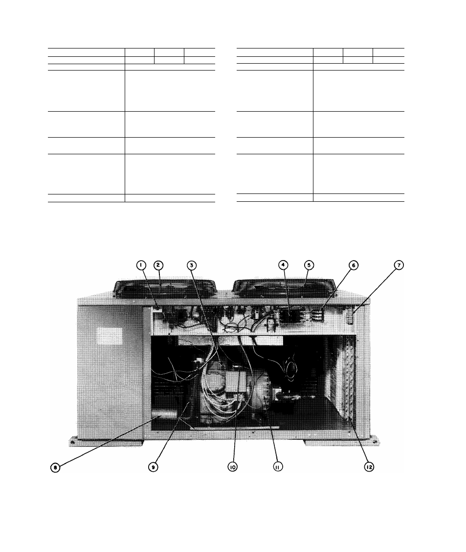
1 -
Low-Voltage Fuse
LEGEND
5 — No. 2 Fan
9
— Hot Gas Bypass Piping Stub (%-in ODM)
2 -
No. 1 Fan
6 — Terminai Biock 1 (Unit Power)
10
— Low-Pressure Switch
3 -
High-Pressure Switch
7 — Terminal Block 2 (Control Power)
11
— Compressor
4 -
Circuit Breakers
8 — Muffler
12
— Wraparound Coil
Fig. 2 — Component Locations