Step 2 — rig and mount the unit a caution, Table 3 - liquid line data – Carrier 38AE User Manual
Page 3
Attention! The text in this document has been recognized automatically. To view the original document, you can use the "Original mode".
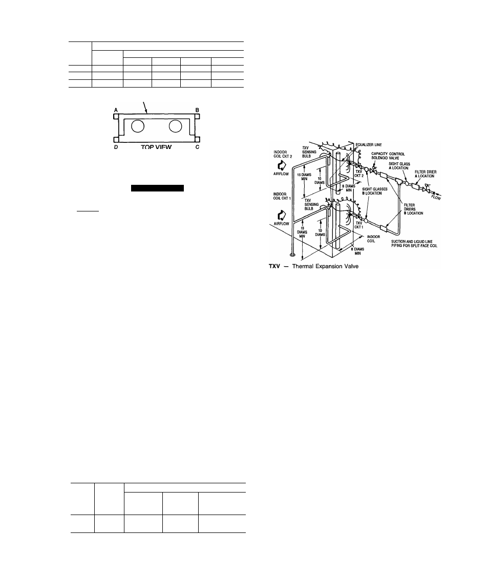
Table 2 — Weight Distribution
r
UNIT
38AE
WEIGHT - lb (kg)
Oper
Wt
Support Point
A
B
C
D
012
732 (333)
142 (65)
138 (63)
225 (102)
227(103)
014
779 (354)
143 (65)
140 (64)
247 (112)
249 (113)
016
789 (359)
143 (65)
143 (65)
250 (114)
253 (115)
COIL
TOP VIEW
Step 2 — Rig and Mount the Unit
A CAUTION
Be sure unit panels are securely in place prior to
rigging.
RIGGING — These units are designed for overhead rig
ging only. For this purpose, the transverse base channels
extend beyond the sides of the unit, with holes provided in
end plates to attach cables or hooks. Rig with top skid pack
aging assembly in place to prevent unit damage by the rig
ging cable. As further protection for the coil faces, plywood
sheets may be placed against the sides of the unit, behind
the cables. Run the cables to a central suspension point so
that the angle from the horizontal is not less than 45 de
grees. Raise and set the unit down carefully.
If it is necessary to roll the unit into position, mount the
unit on longitudinal rails, using a minimum of 3 rollers.
Apply force to the rails, not the unit. If the unit is to be
skidded into position, place it on a large pad and drag it by
the pad. Do not apply any force to the unit.
Raise from above to lift unit from the rails or pad when
unit is in final position.
COMPRESSOR MOUNTING — As shipped, the compres
sor is held tightly in place by self-locking bolts.
Before
starting unit, loosen self-locking boits until the
flanged washer is stiil snug but can be moved side
ways with finger pressure. Do not remove ship
ping bolts.
Step 3
— Complete Refrigerant Piping
Connections
SIZE REFRIGERANT LINES - Consider the length of
piping required between outdoor unit and indoor unit (evap
orator), the amount of liquid lift, and compressor oil re
turn. See Table 3 and also refer to Part 3 of Carrier System
Design Manual for design details and line sizing. Refer to
indoor installation instructions for additional information.
Table 3 - Liquid Line Data
UNIT
38AE
MAX
ALLOW.
LIQUID
LIFT
ft(m)
LIQUID LINE
Max Allow.
Press. Drop
psig (kPa)
Max Allow.
Temp
Loss
•F (”C)
Filter Drier and
Sight Glass
Flare Conn.*
in. (mm)
012
52 (15 8)
7 (48.3)
2(1 1)
%
014
67 (20.4)
7 (48 3)
2(1 1)
Ye
016
82 (25)
7 (48 3)
2(1 1)
Ys
INSTALL FILTER DRIER(S) AND MOISTURE INDICA-
TOR(S) — Every unit should have a filter drier and liquid-
moisture indicator (sight glass). In some applications, de
pending on space and convenience requirements, it may be
desirable to install 2 filter driers and sight glasses. One fil
ter drier and sight glass may be installed at A locations in
Fig. 3. Or, 2 filter driers and sight glasses may be installed
at B locations.
Select the filter drier for maximum unit capacity and min
imum pressure drop. Complete the refrigerant piping from
indoor unit to outdoor unit before opening the liquid and
suction lines at the outdoor unit.
Fig. 3
Locations of Sight Glass(es)
and Filter Drier(s)
INSTALL LIQUID LINE SOLENOID VALVE - SOLE
NOID DROP — It is recommended that a solenoid valve
be placed in the main liquid line (see Fig. 3) between con
densing unit (38AE) and fan coil (40RR, 40RE). This valve
prevents refrigerant migration (which causes oil dilution) to
the compressor during the off cycle at low outdoor ambient
temperatures. The solenoid should be wired in parallel with
the compressor contactor coil. This means of electrical con
trol is referred to as solenoid
drop
control.
INSTALL LIQUID LINE SOLENOID VALVE (OP
TIONAL) - CAPACITY CONTROL - If 2-step cooling
is desired, place a solenoid valve in the location shown in
Fig. 3.
DO NOT USE A RECEIVER — No receiver is provided
with the unit. It is recommended that one
NOT
be used.
MAKE PIPING CONNECTIONS - Do not remove plas
tic dust plugs from suction and liquid line stubs in the com
pressor compartment until piping connections are ready to
be made. Pass nitrogen or other inert gas through piping
while brazing to prevent formation of copper oxide.
Install field-supplied thermostatic expansion valve(s) to
indoor section. If 2 thermostatic expansion valves are in
stalled for 2-step cooling, install field-supplied liquid line
solenoid valve ahead of the second expansion valve.
*lnlet and outlet.
NOTE: Figures shown are for units operating at 45 F (7.2 C) saturated suction
and 95 F (35 C) entering air