Carrier 07E User Manual
Page 6
Attention! The text in this document has been recognized automatically. To view the original document, you can use the "Original mode".
Check low-pressure switch by slowly closing
suction shutoff valve or by completely closing
hquid line shutoff valve. A decrease of suction
pressure will follow. Compressor should shut off
within 4 psi of values shown in Table 1.
HIGH-PRESSURE
SAFETY SWITCH
LOW-PRESSURE
SAFETY SWITCH
RANGE ADJUSTMENT-TURN
CLOCKWISE TO RAISE BOTH
CUT-IN AND CUTOUT
DIFFERENTIAL ADJUSTMENT -TURN
■ № ■' CLOCKWISE TO DECREASE ONLY LOWER
SETTING WITHOUT CHANGING THE
HIGHER SETTING
*Hlgh — 38 PsI/Turn
Low — 7 Psi/Turn
Fig. 8 — Dual Pressurestat Adjustment
Time Guard Circuit
for each compressor provides
for a 5-minute delay before restarting compressor
after shutdown for any reason. On starting, the
Time Guard Timer causes a delay of 15 seconds
after thermostat closes before compressor will
start. On compressor shutdown, the timer recycles
for 4 minutes 45 seconds. During this time the
compressor cannot restart.
Compressor Motor Protection
on 06EW027,
06EW044, 07EB027 and 07ED044 consists of
three temperature sensors embedded in motor
windings and connected to a solid state module in
unit control box.
When an over-temperature condition causes
module to shut compressor off, push control
center STOP button. Investigate cause of com
pressor shutdown and correct. After compressor
cools (see Temperature Sensors below), push
ST ART-RESET button. Compressor will restart
after Time Guard delay period.
SOLID STATE MODULE is checked by applying
unit control voltage to terminals T1 and T2 (see
label diagram), then checking for continuity across
terminals Ml and M2. If no continuity between Ml
and M2, check temperature sensor and fuse resist
ance using a volt-ohmmeter (see below).
CAUTION; Do not use a fcattiary powered test
lamp
to check sensors. Excessive current can
cause damage.
TEMPERATURE SENSORS are protected by
three 1/8-amp fuses (Carrier Part no. HYIOLFOIO)
in compressor terminal box. Fuse resistance should
be between 3.2 and 4.4 ohms. Replace defective
fuses only with 1/8-amp fuses specified above. If
all sensors check below 95 ohms (180 F), fuses are
good, and there is no continuity between module
terminals Ml and M2, replace module.
If one sensor fails, it can be jumpered out of
the circuit with a 75 ohm, 2-watt resistor across
the proper sensor terminal and common terminal.
If a short to ground in sensor circuit is indicated,
replace compressor motor.
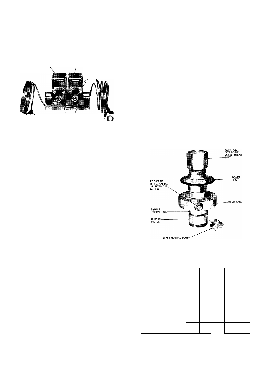
CAPACITY CONTROL ADJUSTMENT
Control Set Point
(cylinder load point) is adjust
able from 0 psig to 85 psig. Pressure differential
between cylinder load-up point and cylinder un
load point is adjustable from 6 psig to 22 psig.
To Regulate Control Set Point
— Refer to Fig. 9.
Turn adjustment nut clockwise to its bottom stop
(with nut in this position set point is 85 psig).
Control set point is then regulated to desired
pressure by turning adjustment nut counterclock
wise; every full turn decreasing set point by 7.5 psig.
(Approximately 11-1/2 turns in counterclockwise
direction will decrease control set point to 0 psig.)
Table 3 shows the steps of control for the
compressor and condensing unit.
SEALING CAP
(CAP MUST BE REPLACED
TO PREVENT REFRIGERANT LEAKAGE)
Fig. 9 — Capacity Control Valve
Table 3 — Steps of Control
COMPRESSOR*
—
1
STEPS
2
--------------- -
3
CONDENSING
UNIT*
No.
Cyl
%
Cap.
No.
Cyl
%
Cap.
No.
Cyl
%
Cap.
06EV022
07EB022
4
100
2
50
-
-
06EW027
07EB027
6
100
4
67
2
33
06EW033
07EB033
6
100
4
67
2
33
06EW044
07ED044
6
100
4
67
2
33
^Capacity control valve (Fig 6) factory settings for 4-cylinder
units are: 69 psig control set point (cylinder load point), 10 psig
differential
(59
psig
cylinder
unload
point)
Settings
for
6-cylinder units are; leit cylinder bank control set point is
70 psig, differential is 10 psig; right cylinder bank control set
point is 68 psig, differential is 10 psig