F e f – Carrier 07E User Manual
Page 10
Attention! The text in this document has been recognized automatically. To view the original document, you can use the "Original mode".
f E f
o-^
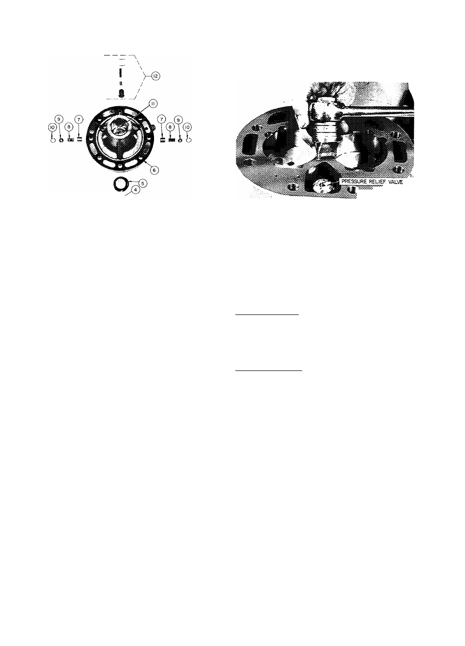
LEGEND
© Pump Vane
® Pump Vane Spring
Pump Vane Spring Guide
(i^ Retaining Spring
© Pump End Main Bearing
(12) Oil Relief Piston
o Cover Plate
Oil Feed Guide Vane Spring
® Oil Feed Guide Vane
® Drive Segment
® Pump Rotor
® Pump End Bearing Plead
Fig. 14 — Pump End Bearing Head Package
CYLINDER HEADS (Fig. 12)
Disassemble cylinder heads by removing cap
screws, and prying up on side lifting tabs to break
heads loose from valve plates. Do not hit cylinder
heads to break loose.
Check heads for warping, cracks and damage to
gasket surfaces. When replacing cylinder head,
torque cap screws 100 to 120 ft-lb (prevents high
to low side leak in center portion of cylinder head
gasket).
Pressure Relief Valve
— This safety device is
located
in
center
cyhnder
bank
(6-cylinder
compressors, Fig. 15) or under discharge service
valve (4-cylinder compressors). The valve relieves
refrigerant pressure from high to low side at
400 psi pressure differential. Check valve for
evidence of leaking. Change if defective or if valve
has ever opened due to excessive pressure. Use a
standard socket-type screwdriver to remove and
replace valve.
Capacity Control Valve(s)
are of the snap-action
type. They are controlled by suction pressure and
actuated by discharge pressure. Each valve controls
Fig. 15 — Pressure Relief Valve Removal
2 cylinders. On start-up, controlled cylinders do
not load up until differential between suction and
discharge pressure is 10 psi (see Fig. 16).
Do not use automatic pumpdown control on
06E, 07E units equipped with unloader valves. Use
single pumpout or solenoid drop (minimum
protection) control.
CAPACITY CONTROL VALVE OPERATION
Loaded Operation — When suction pressure is
above control point, the poppet valve will close.
Discharge gas bleeds into valve chamber, the
pressure closes bypass piston and cylinder bank
loads up. Discharge gas pressure forces check valve
open, permitting gas to enter discharge manifold.
Unloaded Operation — When suction pressure
* *
drops below valve control point, the poppet valve
will open. Discharge gas bleeds from behind bypass
piston to suction manifold. Bypass piston opens,
discharge gas is recirculated back to suction mani
fold and cylinder bank is unloaded. Reduction in
discharge pressure causes check valve to close,
isolating cylinder bank from discharge manifold.
SERVICE REPLACEMENT COMPRESSORS are
* not equipped with capacity control valves. Side
bank cylinder head(s) is plugged with spring loaded
plug piston assembly(ies). Compressor will run
fully loaded with piston plug(s) in place.
Transfer original capaeity control valve(s) to
replacement compressor (ensures proper valves are
used with correct setting). Install plug piston
assembly(ies) into original compressor for sealing
purposes.
Three alien head cap screws hold capacity
control valve in place (Fig. 17). Remove screws
using a “cut down” 3/16-in. alien wrench, and pull
valve from cylinder head.
Remove same number of piston plugs from
replacement compressor as number of unloaders
supplied with original compressor. Three alien head
10