Carrier 07E User Manual
Page 5
Attention! The text in this document has been recognized automatically. To view the original document, you can use the "Original mode".
REFRIGERANT CHARGING
Evacuate, ' Dehydrate and Leak Test
the entire
refrigerant system by methods described in Carrier
Standard Service Techniques Manual, Chapter 1,
Sections 1-6 and 1-7. Use sight glass method to
charge system. See section 1-8 of Service Tech
niques Manual for details.
CHARGE THE SYSTEM to a clear sight glass while
holding saturated condensing pressure constant at
125 F (air-cooled systems) or 105 F (water-cooled
systems). Add additional refrigerant to fill con
denser subcooler coils.
07E Condensing Units
obtained.
After clear sight glass is
until liquid refrigerant
add charge
reaches condenser liquid level test cock.
06E Compressor Units — See condenser data for
additional charge required to fill subcooler.
INITIAL START-UP
Crankcase heater should be energized a mini
mum of 24 hours before starting unit.
Check to see that oil level is 1/3 to 2/3 up on
compressor sight glass.
Open water supply valve and allow water to
reach condenser. (Turn condenser fan on when the
compressor
unit
is
applied
with
air-cooled
condenser.)
Backseat the compressor suction and discharge
shutoff valves; open liquid line valve at receiver.
Start evaporator fan or chilled water pump.
To Start Compressor,
place control center start-
stop switch in “Start” position, and push motor
protector relay start-reset button. (Time Guard
circuit will cause a short delay before compressor
starts.) If compressor does not start in a 5-minute
period, reset oil pressure safety switch and over
load relays.
Recheck oil level and check oil pressure which
should be 12-18 psig above suction pressure.
NOTE: If compressor is shut off by motor
protection relay, current overloads, oil safety
switch or if control circuit power is opened, reset
button(s) must be pushed before compressor will
restart. Do not reset safety controls more than
once before determining cause of shutdown.
CHECKING OPERATIONS
Refer to Carrier Standard Service Techniques
Manual, Chapter 2 for complete instructions on
checking electrical components.
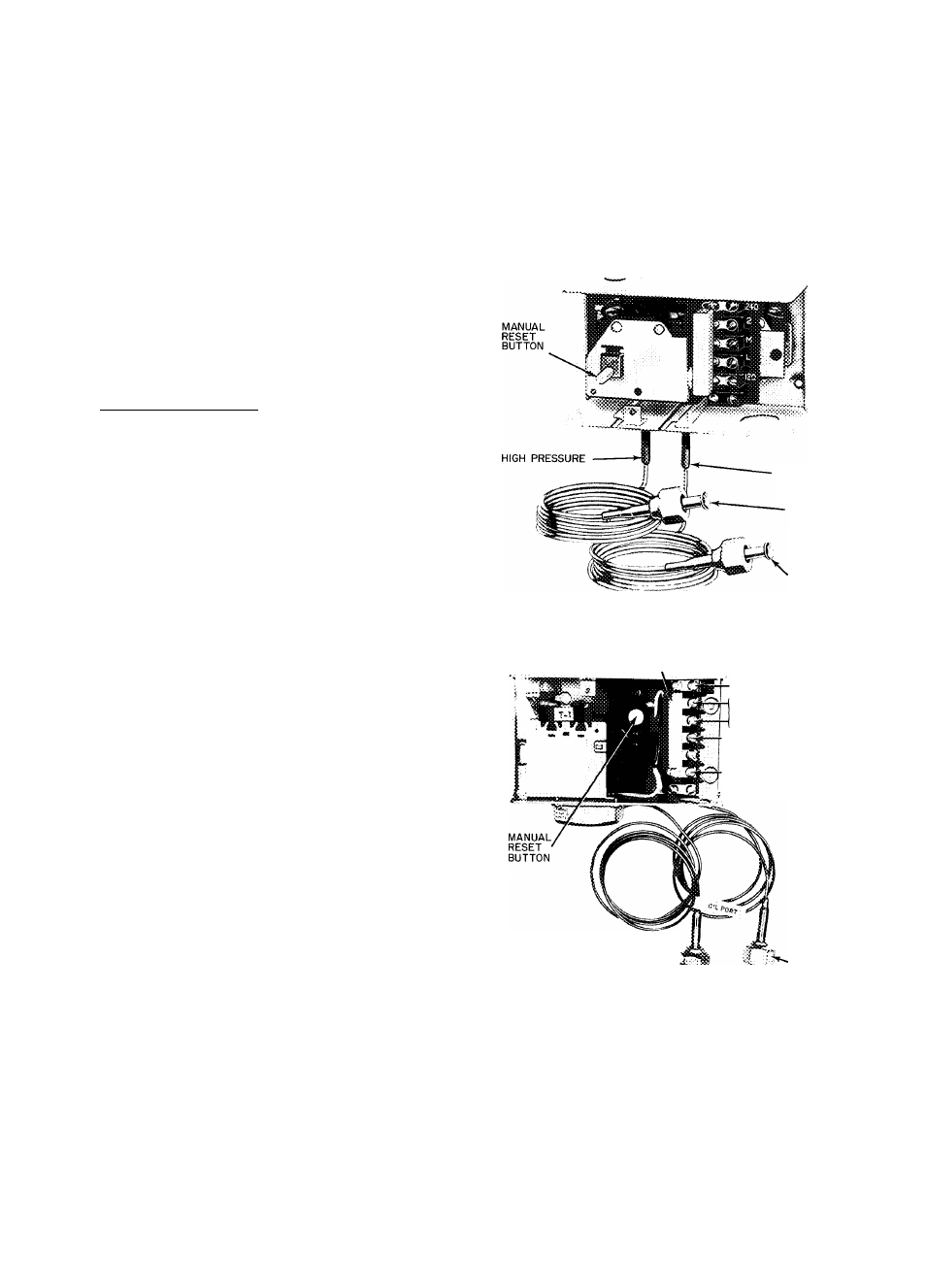
Oil Pressure Safety Switch (Fig. 6 and 7)
may be
checked by moving arm on left side of switch
forward. Compressor should stop in approximately
45 seconds. (If compressor continues to run, check
wiring to safety switch. If wiring is correct, the
switch is faulty and should be replaced.)
After completing test, press reset button on
front of safety switch and restart compressor.
(Allow 3 minutes before attempting to reset
switch.)
NOTE Check oil level in compressor sight glass
after 15-20 minutes of operation. If oil level is low,
add oil according to methods described in Carrier
Standard Service Techniques Manual, Chapter 1
(Section 1-11).
LOW PRESSURE
CONNECT TO
OIL PUMP
DISCHARGE
CONNECT TO
CRANKCASE
(Switch shown is Penn Controls )
Fig. 6 — Oil Pressure Safety Switch Used on;
06EV022, 06EW033, 07EB022, 07EB033
RESISTANCE
■f
CONNECT IN
240
SERIES WITH
VAC
CONTROL CIRCUIT I
120
V^C
(REFER TO UNIT LABEL
WIRING DIAGRAM)
HIGH-PRESSURE
CONNECTION TO
0|LPUMP
'" LOW-PRESSURE
DISCHARGE
CONNECTION
TO CRANKCASE
Fig. 7 — Oil Pressure Safety Switch Used on:
06EW027, 06EW044, 07EB027, 07ED044
Dual Pressurestat (Fig. 8)
— High-pressure safety
switch is checked by throttling condenser water or
blocking air flow on air-cooled units, allowing head
pressure to rise gradually. Check discharge pressure
constantly
throughout
procedure.
Compressor
should shut off within 10 psi of values shown in
Table 1.