50et,qt single-package units – Carrier 50ET User Manual
Page 6
Attention! The text in this document has been recognized automatically. To view the original document, you can use the "Original mode".
HEATING A COOLING
50ET,QT
Single-Package Units
triple-evacuate system to 5000 microns (29.7 in. vacuum)
before recharging. Service port connections are provided
on unit suction and discharge lines for evacuation and
charging. (See Fig. 5 for service port location.) Dial-a-
charge charging cylinder is an accurate device used to
recharge systems by weight. These cylinders are available
at refrigeration supply firms.
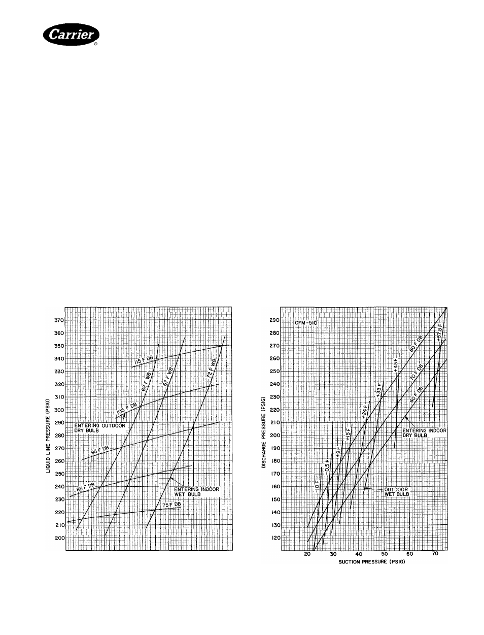
To check and/or adjust charge during cooling season,
use Cooling Cycle Charging Charts (Fig. 6, 8, 10, 12, 14)
and follow Charging Chart Method below. The charging
chart may also be used as an alternate method of recharg
ing system.
To check svsiem operation during heating cycle, use
Heating Cycle Operation Check Chart (Fig. 7, 9, 11, 13,
15). These charts indicate whether a correct relationship
exists between system operating pressures and air tem
peratures entering unit. If pressure and temperature
lines do not intersect on chart, the system refrigerant
charge may not be correct or other system abnormalities
may exist. Do not use Operating Check Charts to adjust
refrigerant charge. Weigh charge into system.
COOLING CYCLE CHARGING CHART
METHOD
1. Operate unit a minimum of 10 minutes before check
ing charge, and after each charge adjustment.
2. Measure suction pressure by attaching a gage to unit
suction service port. (See Fig. 5 for correct service
port location.)
3 Measure outdoor (coil inlet) air dry-bulb tempera
ture. Use service thermometer.
4. Using a sling psychrometer, measure wet-bulb tem
perature of air entering indoor fan coil.
5. Refer to Charging Chart. Locate on curves where
outdoor air dry-bulb and indoor air wet-bulb tem
perature lines intersect.
6. From intersect point, project vertically downward to
chart suction pressure line. Compare chart suction
pressure to unit suction pressure (step 2).
7. If unit suction pressure is lower than chart pressure,
add refrigerant to system until chart pressure is
reached If unit suction pressure is higher than chart
pressure,
remove refrigerant until chart pressure
is reached.
70
72
74
76
78
80
82
84
86
88
90
92
SUCTION PRESSURE (PSIG)
Fig. 6 — 50ET.QT212 Cooling Cycle
Charging Chart
Fig. 7 — 50QT212 Heating Operation
Check Chart
Manufacturer reserves the right to discontinue, or change at any time, specifications or designs without notice and without incurring obiigatlons.
B^k|1
[ 1
|4 |4
PC131 Catalog No 535-078 PrIntedinUSA Form 50ET,QT-3SI Pg6 5-85 Replaces: 50QT-10SI
t
t
Tab ilb|5allal5a
For replacement items use Carrier Specified Parts