System, Accessories, Asmoseo – Carrier WEATHERMASTER 38HQ User Manual
Page 4: System accessories, Physical data and dimensions
Attention! The text in this document has been recognized automatically. To view the original document, you can use the "Original mode".
System
accessories
Hot Shot heat reclaim device Utilizes hot dis
charge gas irom heat pump system to preheat
domestic hot water supply Conserves energy
required to operate water heater
1 ? ’
allows for cycling or continuous indoor fan
operation
Outdoor
— Provides for staging of
electric resistance heaters By using these
specially developed heat pump thermostats, the
ability to call for emergency electric heat, if
required, becomes a standard feature of the
38HQ dual-compressor system
THERMOSTAT
HOT SHOT
HEAT RECLAIM
DEVICE
Thermostat packages
Indoor
—
2-stage
heating, 2 stage cooling thermostat provides
manual or automatic changeover from cooling to
heating, maintains comfortable indoor tempera
ture by controlling compressor operation, deter
mines need for electric resistance heating, and
Emergency heat relay When activated by
emergency heat switch on indoor thermostat, this
relay provides immediate electric heater opera
tion during heat pump shutdown
Liquid line filter-drier keeps refrigerant circuit
free of moisture and contaminants
Precharged tubing packages are available in
15, 20, 25, 35, 40, and 50-ft lengths to save installa
tion time (Vapor line must be sectioned at com
pressor section )
Heat pump rack elevates outdoor section in
areas of heavy snowfall
Solid State Time Guard 11® device prevents
potential compressor damage caused by rapid
cycling Requires a five-minute delay before
restarting
Optimizer control is used when the 38HQ heat
pump is added to an existing gas or oil furnace
Provides heating as requited, and maximizes
system usage, when the heating system is acti
vated When indoor thermostat calls for heating,
the Optimizer energizes the heat pump When
outdoor temperature drops below second ther
mal balance point, the Optimizer shuts off both
compressors and energizes furnace Also oper
ates furnace during heat pump defrost cycle to
temper indoor air
OPTIMIZER
Elare-to-compatible coupler converts
line connection to a Compatible Fitting
liquid
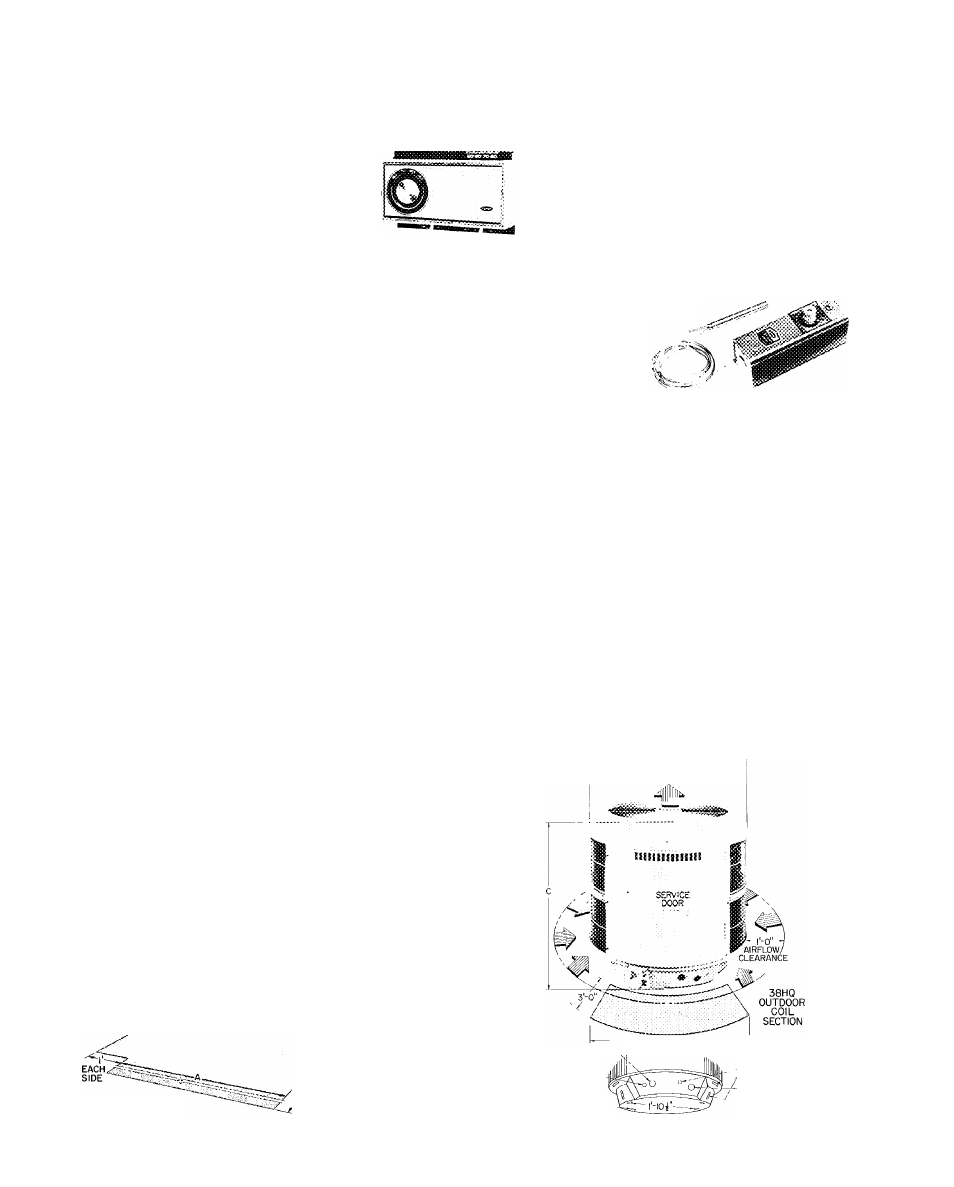
Physical data and dimensions
INDOOR COMPRESSOR SECTION
OUTDOOR COIL SECTION
UNIT......................................
pp’ERAT(N(3 Wf7ibT..............
REFRIGERANT
COMPRESSOR
Cylinders
Rpm (60-Hz)
dimensions
(ft-in )
Width
A
Depth
B
Height
C
VAPOR LINE CONN (in ODF)
Vapor Lines (2)*
^HQ2^
”205
3SH0234
225
22
Hermetic
2
3500
2-2-3/32
1-4-3/16
-11 -1 /8 (Add 3/4-in. for Refrig Fittings)
Compatible Fittings (2)
‘Recommended Refrigerant Line Sizes:
INDOOR COMPR SECT
OUTDOOR COIL SECT
VAPOR
(in 65)
LIQUID
(in 65)
3/4
38HQ227
38HQ940
3 '4
1-1/S
38HQ234
38HQ960
1
-
1 / 8
3/8
UNIT
*6
p
T
r
a
T
in
'
g
'
wt
7
i
¿y
REFRIGERANT*
Refrig Control
FAN
Air Discharge
Air Quantity (cfm)
Motor Rpm (60-Hz)
Motor Hp
COIL (Type)
Fins/in
Face Area (sq ft)
Rows
5rMENSiONS (ft-in )
Diameter
Height
Mtg Slots
CONl^ECtiONS (in )
Vapor Linet
Liquid Linet
38HO340
asMOseo
107
,
125
22
AccuRater^'^ device
Propeller-Type, Direct Drive
Vertical
3100
1015
1/5
19
10 5
2
2- 5-1/4
2-8
1
-1 0 -1 / 2
Plate Fin
3600
1080
1/4
17
15 3
2
2- 5-1/4
3-8
1
-
10
-
1/2
Compatible Fitting (Vapor)
and Flare (Liquid)
3/4
3/8
‘The 38HQ234 system requires 1-1/8 in vapor line for optimum perfor
mance If using 7'8-in vapor line, deduct 1-1 2% of rated capacity for
every 25 ft of I un The 38HQ234 is supplied with four 3/4 x 1-1 8in con
nection adapters (field installed) for 1-1 ''8 in vapor line
NOTES
1
Maximum allowable liquid line length is 1 00 feet Maximum vapor line
length from compression unit to indoor coil is 50 feet Maximum vapor
line length from compression unit to outdoor coil section is 50 feet
2
Maximum allowable vertical separation of indoor unit above or below
outdoor unit is 50 feet
*The 38HQ outdoor coil contains correct operating charge for complete
system when connected to 40FS/28HQ,VQ indoor units with 25 ft
or less of tubing of recommended diameter
tSee recommended refrigerant line sizes under Indoor Compressor
Section Physical Data table
4-0"OVERHEAD
SPACE REQUIRED
FOR SERVICE AND AIRFLOW
VAPOR LINE-
CONN. TO
INDOOR COIL
TOP
"
COVER
ACCESS
WRAPPER
VAPOR LINE
-CONN TO
OUTDOOR COIL
li DIAM H0LE(0R l| KO)
rFOR COMPR SECT LINE
\ POWER WIRING
foiAM HOLE (OR
li' KO) FOR
OUTDOOR FAN
COIL SECT. LINE
POWER WIRING
(SEE ELEC DATA
.WIRING)
f DIAM HOLE
FOR CONTROL
WIRING
SPACE
REQUIRED
FOR SERVICE
B 38HQ
/ INDOOR
■V COMPRESSOR
/3‘ SECTION
------- 3-0"-------------
VAPOR LINE CONN (ON SERVICE VALVE)
LIQUID LINE
CONN
Certified dimension drawings available on request
d- If
MTG SLOTS
(USE ANY 2TO ---
BOLT UNIT DOWN)
SPACE REQUIRED FOR SERVICE AIRFLOW
Certified dimension drawings available on request
i DIAM HOLE
FOR CONTROL
WIRING
DRAINAGE HOLES
— If DIAM
HOLE FOR
POWER WIRING