Carrier 38AQ034 User Manual
Page 5
Attention! The text in this document has been recognized automatically. To view the original document, you can use the "Original mode".
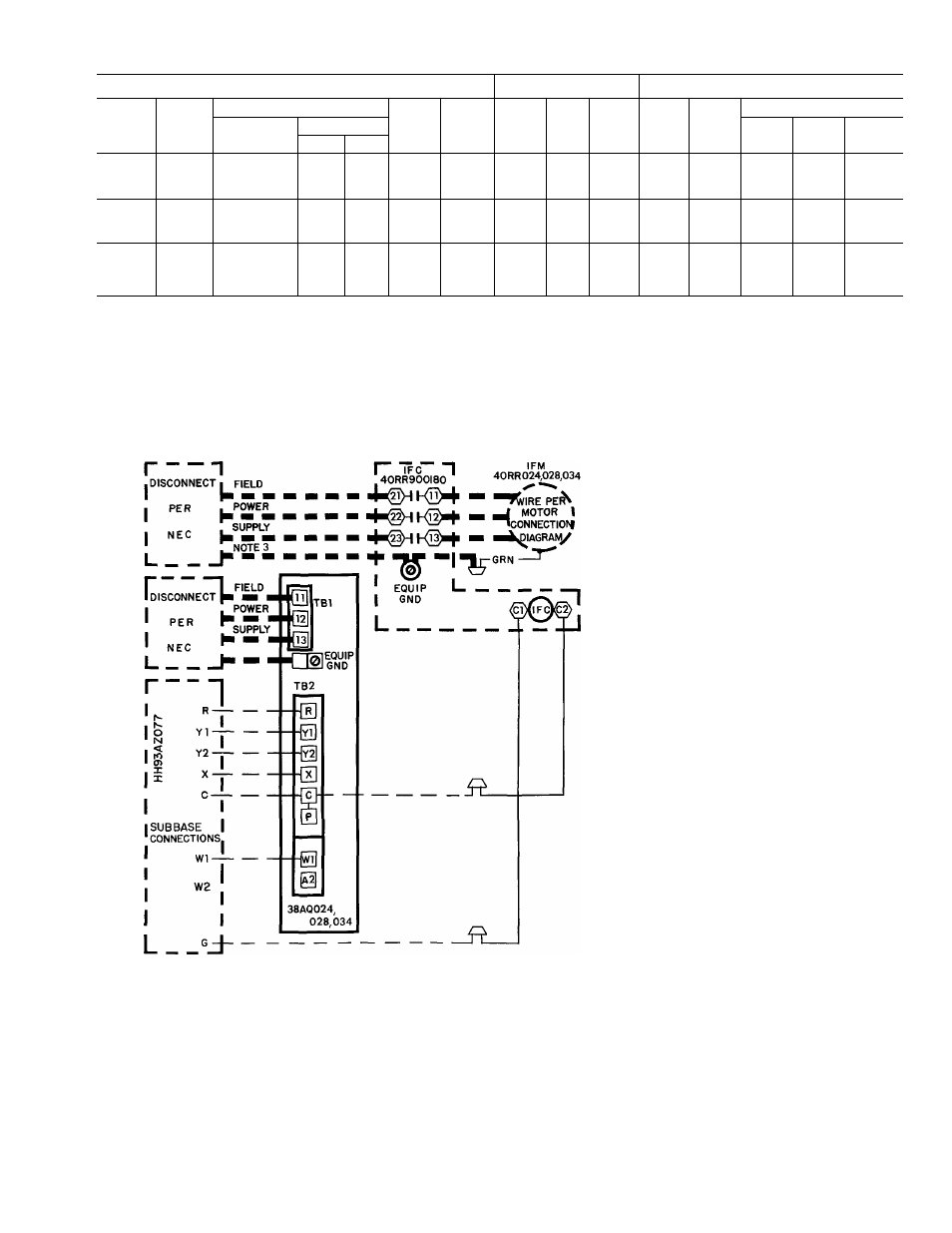
Table 6 — Electrical Data (3 Phase, 60 Hz)
UNIT
COMPRESSOR
FANS
38AQ
Model
Volts
MCA
MOCP
RLA
LRA
MTA
Total
Kw
(total)
FLA (ea)
Nameplate
Supplied*
No. 1
No 2
No. 3
Min
Max
510
208/230
187
253
103
175
76 0
345
53t
45
4 6
46
024
600
460
414
508
51
80
36 0
173
50t
3
3 4
1 9
1 9
1 9
100
575
518
632
41
60
28 6
120
40t
1 6
1.6
1.6
510
208/230
187
253
145
225
100 0
446
70t
6 2
6 6
6 6
028
600
460
414
508
69
110
48 0
223
33t
3
34
3 0
3 0
3 0
100
575
518
632
62
100
43.4
164
6;t
2.5
2.5
2.5
510
208/230
187
253
170
250
120 0
506
84Н
6 2
6 6
6 6
034
600
460
414
508
72
110
50 0
253
35Н
3
3 6
30
3 0
3 0
100
575
518
632
64
100
45 0
176
63t
2 5
2 5
2 5
FLA — Full Load Amps (fan motors)
LRA — Locked Rotor Amps
MCA — Minimum Circuit Amps Compiles with NEC Section
430-24
MOCP — Maximum Overcurrent Protection (fuse only)
MTA — Must Trip Amps (circuit breaker)
NEC — National Electric Code
RLA — Rated Load Amps (compressor)
'Units are suitable for use on electrical systems where voltage
supplied to the unit terminals is not below or above the listed
limits
t3-Pole circuit breaker
^6-Pole circuit breaker
LEGEND
Equip Gnd — Equipment Ground
IFC
— Indoor Fan Contactor
IFM
— Indoor Fan Motor
TB
— Terminal Block (Board)
NOTES
1 This diagram applies to the follow
ing systems. 40RR024 with 38AQ
024, 40RR028 with 38AQ028 and
40RR034 with 38AQ034.
2. For wiring details of components,
see schematic in each component
3 Use copper conductors only for IFM
wiring
Fig. 6 — System Label Diagram; 38AQ024,028,034
NOTES
,—I
1 Locate blue wire between [jJ on TB2B and terminal 7 of CR3
and cut
2 Splice airflow switch (AFS) (field supplied) contact wires (field
provided) to 2 ends of cut blue wire as depicted
AFS
— Airflow switch (sail switch)
---------- Factory Wiring
-----------Field Wiring
TB2B
BLU
^SPLICE^
I
I
I
AFS
I
CR3
BLU
Fig. 7 — Field Wiring for Airflow Switch. 38AQ024, 028 or 034/40RR