Step 5 — make electrical connections – Carrier 38AQ034 User Manual
Page 4
Attention! The text in this document has been recognized automatically. To view the original document, you can use the "Original mode".
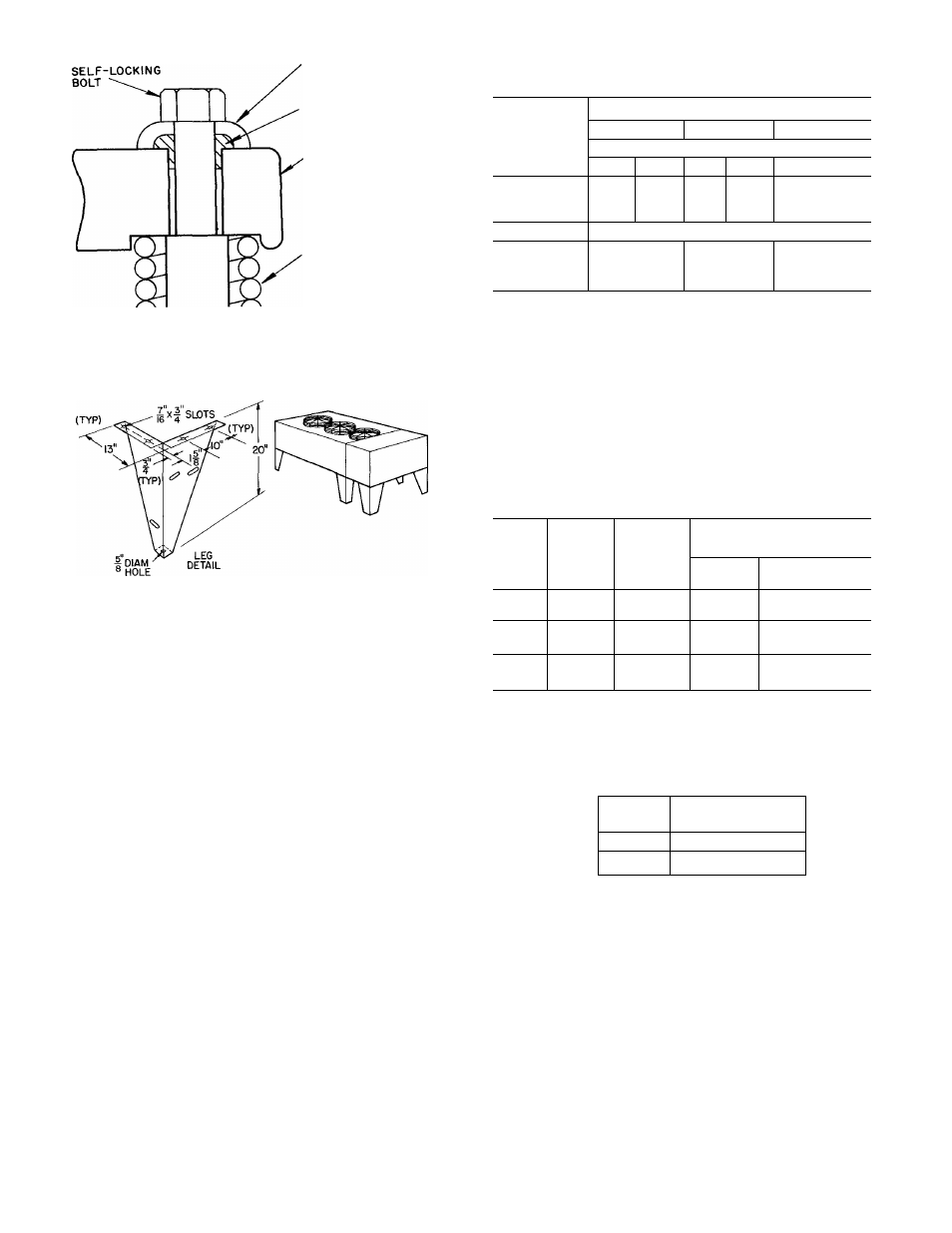
SNUBBER
FLANGED
WASHER
.
neoprene
SNUBBER
Table 3 — Refrigerant (R-22) Charge and
Piping Selection Data
ISOLATION SPRING
Fig. 4 ~ Compressor Mounting
NOTES
1 For mounting dimensions, see Fig 1.
2 Parts package contains all fasteners required for assem
bling 20-in. legs to unit
Fig. 5 — Mounting Legs for 38AQ Units
Step 5 — Make Electrical Connections
POWER
SUPPLY
—
Electrical
characteristics
of
avail
able
power
supply
must
agree
with
nameplate
rating.
Supply
voltage
must
be
within
tolerances
shown
in
Tableó.
See
Fig.
6
for
System
Label
Diagram.
Phase
unbalance
must
not
exceed
2%.
Operation
of
unit
on
improper
supply
voltage
or
with
excessive
phase
un
balance constitutes abuse and is not covered by Carrier
Warranty.
POWER
WIRING
—
All
power
wiring
must
comply
with
applicable
local
requirements
and
National
Elec
trical Codes. Install a field-supplied branch circuit dis
connect switch of a type that can be locked OFF or
OPEN. Run power wires from disconnect switch through
unit power opening (D on Fig 1 ) and connect to terminal
block
just
inside
opening.
See
Table
5
for
maximum
allowable wire size.
Power terminal block is in the control box. Remove
outer panel and #10 screw on the door. Swing door open,
remove screws on barrier panel and remove barrier panel.
Replace barrier panel when power wiring is completed.
Condenser
fans
must
rotate
clockwise
when
viewed
from above. If necessary, correct direction of fan rotation
by reversing any 2 power input wires at disconnect switch.
Affix crankcase heater decal to unit disconnect switch.
CONTROL
CIRCUIT
WIRING
—
Internal
control
voltage on 38 AQ units is both 115-volts and 24-volts. All
control circuit wiring must comply with applicable local
LENGTH OF PIPING (ft)*
OUTDOOR
0-25
26-60
61-100t
UNIT
38AQ
Line Size (in. O.D.)
L
V
L
V
L V
024
%
1%
%
1%
% 1 %
028
%
1%
%
1%
V
b
2 Va
034
%
U/s
%
2'/8
%
2'/8
Approximate System Charge (lb)t
024
55
58
75
028
61
65
83
034
71
79
93
L
— Liquid Line
V
— Vapor Line
'Approximately 4 elbows assumed in determining pipe sizes
fMaximum length of interconnecting piping is 100 feet.
^Approximate system charge is for estimating only It includes
charge requirements for one outdoor unit, matching indoor coil,
and interconnecting piping System should be charged in
accordance with installation instructions
NOTE Maximum liquid line size is %-in OD Maximum R-22
system charge is 85 lb (024), 95 lb (028), 105 lb (034)
Table 4 — Minimum Outdoor Air Operating
Temperature
MINIMUM OUTDOOR
UNIT
COMPR
CONO
TEMPERATURE (F)*
38AQ
CAP. (%)
TEMP (F)
Std Unit
32LT
Motormaster®
024
100
90
28
-20
50
80
41
-20
028
100
90
34
-20
67
80
37
-20
034
100
90
30
-20
67
80
33
-20
'Applies to cooling mode of operation only
Table 5 — Maximum Allowable Field Wire Sizes
UNIT
38Aa
024,028,034
VOLTS
(60-Hz)
WIRE SIZE
208/230
6 AWG to 350 MCM
460, 575
14 AWG to 2/0
CONN.
TB
TB
Terminal Block (with integral compression terminal)
and national codes. Route remote control wiring to unit
control box through control opening (C on Fig. 1) and
connect to control terminal block inside the control box.
All external control wiring is 24-volt, NEC Class 2.
SAIL
SWITCH
—
It
is
highly
recommended
that
an
indoor
airflow
switch
(field
installed)
be
installed
and
interlocked with the outdoor unit, to prevent the outdoor
unit from operating in the event of indoor airflow failure
(example: broken fan belt). Operation of compressor with
no
indoor
airflow
causes
compressor
to
operate
in
a
vacuum
which
can
damage
bearing
surfaces.
Therefore,
install a field-supplied sail switch in the supply air duct
work of the mating indoor fan coil unit, and wire to
outdoor unit. See Fig 7.
.4^