Fig. 12 — typical heat pump operation – Carrier 38AQ034 User Manual
Page 11
Attention! The text in this document has been recognized automatically. To view the original document, you can use the "Original mode".
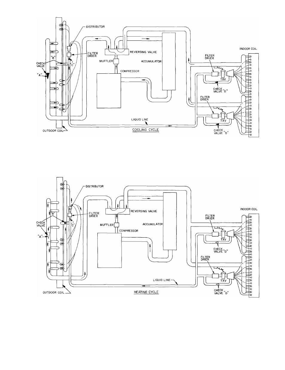
Hot gas from compressor flows through the 4-way valve and is
directed to the outdoor coil header At the header it is con
densed and subcooled through converging circuits Refrig
erant leaves the outdoor coil by way of the check valve to the
liquid line
The refrigerant then fiows through the filter drier and feeds the
indoor coil by way of capillary tubes on each circuit
3 Each circuit evaporates the refrigerant and the circuits are
combined in the indoor coil header
4 The refrigerant then flows through the 4-way valve, accu
mulator and back to the compressor.
Hot gas from compressor flows through the 4-way valve and is
directed to the indoor coii header At the header it is con
densed and directed through subcooling circuits and out the
indoor coil check valve to the liquid iine. (The TXV’s stop
the refrigerant fiow during the heating cycle )
The refrigerant then feeds the outdoor coil by way of a strainer
and then through capiliary tubes on each circuit
Each circuit evaporates the refrigerant and the circuits are
combined in the outdoor header with some of the circuits
flowing through the check valve
The refrigerant then flows through the 4-way valve, accu
mulator and back to the compressor
NOTES:
1 Check valves are designated “A” through “D ”
2. Illustrations are typicai and do not portray exact coil circuiting
3 Check valve positions:
A
open,
A
closed.
4 Only one outdoor coil is shown above The 38AQ024,028 and
034 have 2 coils plus 2 of each check valve shown above
Fig. 12 — Typical Heat Pump Operation
11