Carrier 50DPE014 User Manual
Page 7
Attention! The text in this document has been recognized automatically. To view the original document, you can use the "Original mode".
10
(J'IFPT
DRAIN CONNECTION^ L
(HALF COUPLING) "V
BASE RAIL-
u
TO TRAP -O'
Fig. 9 — Condensate Drain Piping Details
Step
6
— Make Electrical Connections
FIELD POWER SUPPLY — Unit is factory wired for
voltage shown on nameplate. Units are provided with
terminal block.
When installing units, provide a disconnect per NEC
of adequate size (Table 2).
All field wiring must comply with National Electrical
Code and local requirements.
Route power lines through control box end panel — or
unit basepan — (Fig. 4) to terminal connections as shown
on unit wiring diagram and Fig. 10.
I----------1
TBI
ÜO I
U
z ^ I
o
q
: I
U liJ I
OT a.
o '
I
_____ I
FIELD
11
21
POWER
12
22
SUPPLY
13
23
EQUIP GND
Fig. 10 — Field Power Wiring Connections
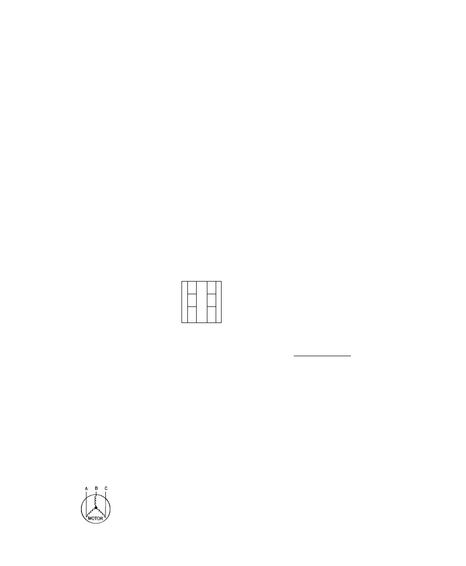
Operating voltage to compressor must be within
voltage range indicated on unit nameplate. On 3-phase
units, voltages between phases must be balanced within
2% and the current must be balanced within 10%.
Use the following formula to determine the % voltage
imbalance.
% Voltage Imbalance
100
X
voltage
average voltage
Example: Supply voltage is 460-3-60.
AB = 452 volts
BC = 464 volts
AC = 455 volts
Average Voltage =
452 + 464 + 455
1371
457
Determine maximum deviation from average voltage:
(AB) 457 - 452 = 5 volts
(BC) 464 - 457 = 7 volts
(AC) 457 - 455 = 2 volts
Maximum deviation is 7 volts.
Determine % voltage imbalance:
7
% Voltage Imbalance = 100 x-
457
1.53%
This amount of phase imbalance is satisfactory as it is
below the maximum allowable 2%.
IMPORTANT: If the supply voltage phase im
balance is more than 2%, contact your local electric
utility company immediately.
Unit failure as a result of operation on improper line
voltage or excessive phase imbalance constitutes abuse
and may cause damage to electrical components. Such
operation would invalidate any applicable Carrier
warranty.
FIELD CONTROL WIRING — Install a Carrier-
approved accessory thermostat assembly according to
installation instructions included with accessory. Locate
thermostat assembly on a solid wall in the conditioned
space to sense average temperature.
Route thermostat cable or equivalent single leads of
no. 18 AWG colored wire from subbase terminals
through conduit in unit to low-voltage connections as
shown on unit label wiring diagram and in Fig. 11.
NOTE: For wire runs up to 50 ft, use no. 18 AWG insu
lated wire (35 C minimum). For 50 to 75 ft, use no. 16
AWG insulated wire (35 C minimum). For over 75 ft, use
no. 14 AWG insulated wire (35 C minimum).
Set heat anticipator settings as indicated in Table 3.
Settings may be changed slightly to provide a greater
degree of comfort for a particular installation.
Refer to accessory remote control panel instructions
as required.
THERMOSTAT ASSEMBLY
REMOVABLE JUMPER
^ ^ 1^ ^ ^
[
r
] [
b
] É I 1 И Й ] Й Й 1 [
c
] É 1 Q
l
1 [ ] 3 ] @
Q
llJ
q
:
Z)
_l
m
LOW-VOLTAGE TERMINAL BLOCK IN UNIT CONTROL BOX
Fig. 11 — Field Control Thermostat Wiring
Step 7 — Make Outdoor Air Inlet Adjustments
MANUAL OUTDOOR AIR DAMPER — All units
(except those equipped with a factory-installed econo
mizer) have a manual outdoor air damper to provide
ventilation air. Damper can be preset to admit up to 25%
outdoor air into return air compartment. To adjust,
loosen securing screws and move damper to desired
setting then retighten screws to secure damper (Fig. 12).
OPTIONAL ECONOMIZER
Enthalpy Control Setting (location is shown in Fig. 13) —
For maximum benefit of outside air, set enthalpy control
to the A setting (Fig. 14).