Carrier 50DPE014 User Manual
Page 2
Attention! The text in this document has been recognized automatically. To view the original document, you can use the "Original mode".
NOM I^"x4"
(32) X (102)
TYP. 4 PLACES
ROOF OPENINGS
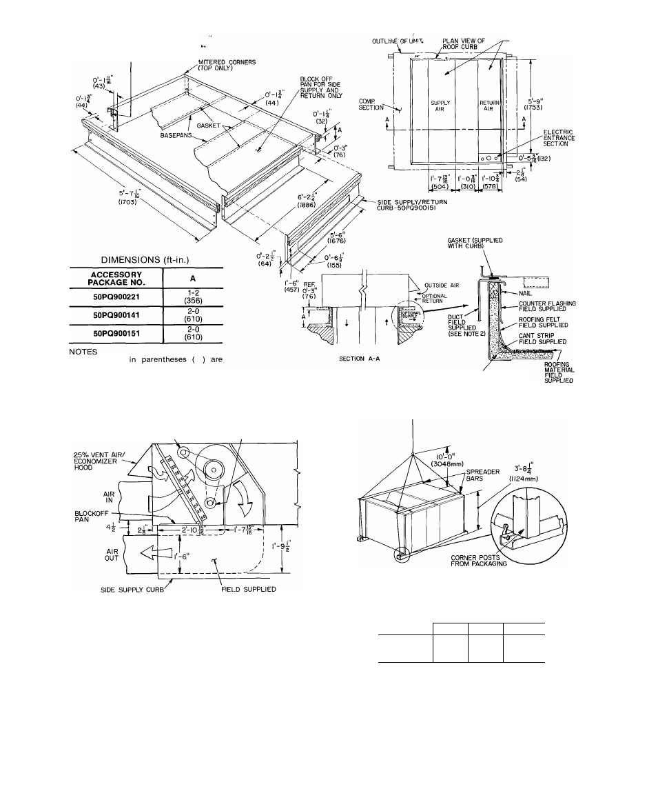
Dimensions
miilimeters.
Attach aii ductwork to roof curb
Fieid installation of sidewall insulation
is mandatory
INDOOR AIR
FAN MOTOR
INSULATION
FIELD
SUPPLIED
(SEE NOTE 3)
Fig. 1 — Roof Curb Details
INDOOR AIR
FAN MOTOR
50DP020
(50PQ900I5I)
TRANSITION DUCT
RIGGING WEIGHTS* (lb)
Fig. 2 — Side Supply/Return Curb Details
MODEL
COIL FIN MATERIAL
OUTDOOR/INDOOR
AI/AI
Cu/AI
Cu/Cu
50DPE014
1880
1960
2040
50DP016
1880
1960
2040
50DP020
2390
2520
2630
Do not install unit in an indoor location. Do not locate
unit air inlets near exhaust vents or other sources of
contaminated air.
Although unit is weatherproof, guard against water
from higher level runoff and overhangs.
ROOF MOUNT — Check building codes for weight dis
tribution requirements. Unit weight is shown in Table 1.
'Includes economizer weight
NOTE Rig by inserting hooks Into unit base rails as shown Main
tain a distance of 120 in (3048 mm) from top of unit to eyehook
Use corner post from packaging to protect coil of unit from
damage by rigging cable. Use bumper boards for spreader bars
CAUTION!
All panels must be in place when rigging.
Fig. 3 — Rigging Details
©