Carrier 50DPE014 User Manual
Page 10
Attention! The text in this document has been recognized automatically. To view the original document, you can use the "Original mode".
Step
8
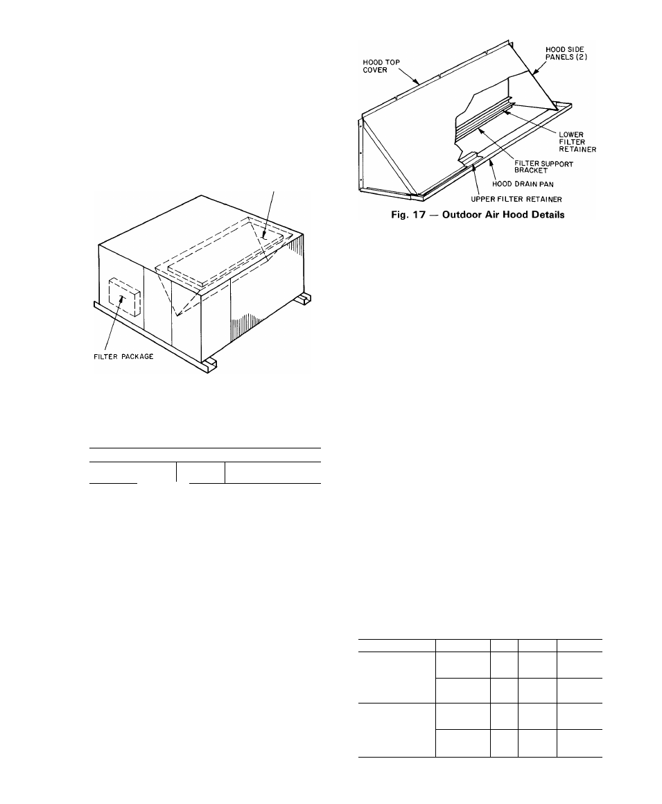
— Install Outdoor Air Hood
— The out
door air hood is common to 25% air ventilation and
economizer. If economizer is used, all electrical connec
tions have been made and adjusted at the factory.
Assemble and install hood in the field.
NOTE: The hood top cover, upper and lower filter
retainers, hood drain pan and filter support bracket are
secured to the top crate above the condenser fans. The
screens, hood side panels, remaining section of filter
support bracket and all other hardware are in a package
located inside the return-air filter access panel (Fig. 15
and 16).
OUTDOOR AIR HOOD AND
MOUNTING BRACKETS
Fig. 15 — Outdoor Air Hood
Component Location
UNIT TOP CRATE
L
'i
/ \
/---------------------
UPPER FILTER
RETAINER
X /
/ I nVA/PR
LOWER
FILTER
RETAINER
FILTER
SUPPORT
BRACKET
HOOD TOP
COVER
Fig. 16
HOOD DRAIN PAN
Outdoor Air Hood Components
START-UP
Unit Preparation
— Check that unit has been installed
in accordance with installation instructions and appli
cable codes.
Compressor Mounting
— Loosen compressor hold
down bolts until sidewise movement of the washer under
each holddown bolt head can be obtained. Do not
loosen completely as bolts are self-locking and will main
tain adjustment.
Internal Wiring
— Check all electrical connections
in unit control boxes; tighten as required.
Refrigerant Service Valves
— The units have one
service valve on suction line, one on discharge line
and one on liquid line. Be sure valves are open.
Crankcase Heater(s)
are energized as long as there is
power to the unit.
NOTE: Unit power must be on for 24 hours prior to
start-up.
1. Assemble hood top cover, side panels, upper filter
retainer and drain pan (Fig. 17).
2. Secure lower filter retainer and support bracket to
unit as shown in Fig. 17.
3. Loosen sheet metal screws for base unit top cover
located above outdoor air inlet opening.
4. Match notches in hood top cover to unit top cover
screws. Insert hood flange between unit top cover
flange and unit. Tighten screws.
5. Insert outdoor air inlet screens and spacer in channel
created by lower filter retainer and filter support
bracket.
6. Attach remaining section of filter support bracket.
Table 3 — Heat Anticipator Settings
UNIT MODEL
VOLTAGES
kW
STAGE 1 STAGE 2
14-17
40
—
208-230/3/60
26-31
40
40
50DPE014
42-52
66
40
16
40
—
460/3/60
30
.40
40
51
40
66
26-31
40
66
208-230/3/60
42-52
66
.40
50DP016.020
56-69
66
66
30
40
40
460/3/60
51
40
66
73
.66
66
K
10