Carrier 50DPE014 User Manual
Page 15
Attention! The text in this document has been recognized automatically. To view the original document, you can use the "Original mode".
Economizer Adjustment
1. Set enthalpy control at its highest setting. If outdoor
temperature is above 70 F, perform the following;
install jumper between enthalpy control terminals 1
and 2 (red and yellow wires).
2. Set system selector switch at COOL and set cooling
selector lever at lowest setting. (Cooling mode may be
simulated by removing thermostat wires from termi
nals Y1 and Y2 [if used] and installing jumper between
Y1 and R.)
3. Set mixed air thermostat (MAT.) at lowest setting.
Outdoor air damper goes to fully open position
(indoor air damper closes).
4. Set mixed air thermostat at highest setting. Outdoor
air damper goes to fully closed position (indoor air
damper opens).
5. Adjust mechanical linkage for correct positioning
if necessary. If cooling was simulated in 2, remove
jumper and reconnect thermostat wire(s).
Power Failure
— Dampers do not have a spring
return. In event of power failure, dampers remain in
position until power is restored. Do not manually
operate damper motor.
50DP020 Indoor Air Fan Motor Removal
NOTE; To remove belts only, follow steps 1 - 4.
1. Remove filter and supply air section access panels.
Remove center post (Fig. 4).
2. Loosen adjusting nuts A and E, Fig. 23.
3. Push motor away from indoor coil to zero adjustment.
Tighten nut A.
4. Remove belts from pulleys.
5. Remove holddown screws at B and C. Loosen screw
at D.
6. Holding motor and pulley securely, slide motor
mount assembly out of unit along slide tracks.
NOTE; To reinstall motor, reverse above procedure.
Refrigerant Charge
— Amount of refrigerant charge
is listed on unit nameplate and in Table 1. Refer to Carrier
Standard Service Techniques Manual, Chapter I,
Refrigerants.
Unit panels must be in place when unit is operating
during charging procedure.
NO CHARGE — Use standard evacuating techniques.
After evacuating system, weigh in the specified amount of
refrigerant. (Refer to Table 1.)
LOW CHARGE COOLING — Using appropriate cool
ing charging chart. Fig. 24 or 25, add refrigerant until
conditions of the chart are met. Note that charging charts
are different from ones normally used. Charts are based
on charging units to correct superheat for various
operating conditions. An accurate pressure gage and
temperature sensing device are required. Connect tem
perature sensing device to service port on suction line and
insulate it so that outdoor ambient temperature does not
affect reading. Indoor air cfm must be within normal
operating range of unit.
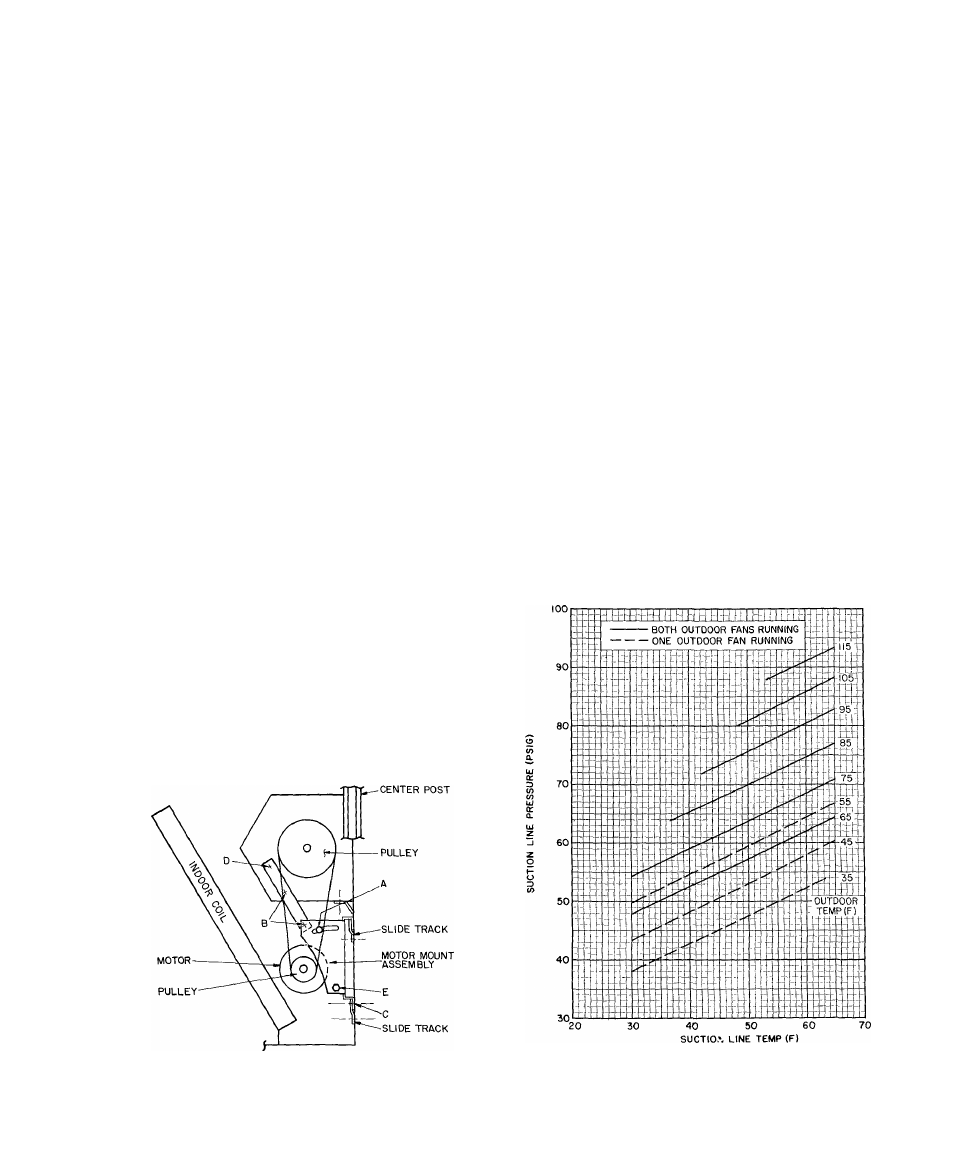
TO USE COOLING CHARGING CHART — Take
outdoor ambient temperature and read the suction
pressure gage. Refer to ehart to determine correct
suction temperature. If suction temperature is high, add
refrigerant. If suction temperature is low, carefully blow
some of the charge. Recheck suction pressure as charge
is adjusted.
Example; Fig. 24 — 50DPE014
Outdoor Temperature............................................85 F
Suction Pressure.............................................. 75 psig
Suction Temperature should be............................ 60 F
(Suction Temperature may vary ± 5 F.)
If Chargemaster® charging device is used, temperature
and pressure readings must be accomplished using
appropriate charging chart.
Fig. 23 — 50DP020 Indoor Fan Motor Section
Fig. 24 — Cooling Charging Chart —
50DPE014, 50DP016
15