Leak test and dehydration, Charge machine with water – Carrier 17DA User Manual
Page 4
Attention! The text in this document has been recognized automatically. To view the original document, you can use the "Original mode".
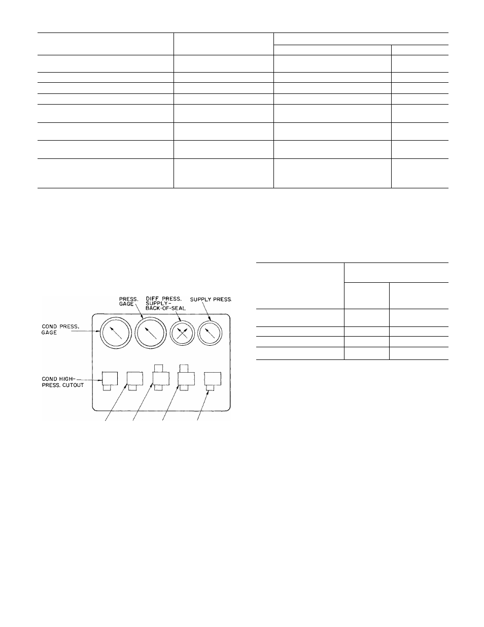
Table 2 — Control Settings
CONTROL
LOCATION
SETTING
British Values
Metric Values
Low Chilled Water Temperature
Cutout
Cooler Water Box
38 F or 5 F lower than brine
temperature
1.7 C
High Discharge Gas Temperature Cutout
Compressor End Wall
240 F
115 C
High Thrust Bearing Temperature
Compressor Bearing Chamber 180 F
82.5 C
High Condenser Pressure Cutout
Control Panel
165 psig
11.6 kg/sq cm
Low Cooler Pressure Cutout
Control Panel
Vendor set at 35 psig. Reset 2 psi
below normal suction pressure.
2.45 kg/sq cm
. 14 kg/sq cm
Low Seal Oil Pressure Cutout
Control Pane!
Open 11 psid
Close 16 psid
.76 kg/sq cm
1.16 kg/sq cm
Low Bearing Oil Pressure Cutout
Control Panel
Open 8 psig
Close 13 psig
.56 kg/sq cm
.90 kg/sq cm
Auxiliary Oil Pump
Differential Pressure
Control Switch
Control Panel
Open 27 psid
Close 23 psid
1.90 kg/sq cm
1.60 kg/sq cm
4.
5.
6
.
Oil low-pressure switches
Condenser high-pressure cutout
Check the following optional safety devices:
a. Brine flow switch
Condenser water flow switch
Condenser refrigerant level switch
Drive protection devices
Pump interlocks
Special interlocks, timers, etc.
b.
c.
d.
e.
f.
COOLER SEAL OIL
BEARING OIL
COOLER AUXOIL LOW SEAL LOW BEARING
LOW-PRESS. PUMP OIL PRESS. OIL PRESS.
CUTOUT CONTROL CUTOUT CUTOUT
Fig. 1 — 17DA Safety Instrument Panel
MOTOR DRIVE — Disconnect the main motor
leads at the starter to check out the safety controls
without operating the motor. Disconnecting the
leads to the starter holding coil will accomplish the
same purpose. Place a volt-ohmmeter across the
open leads. The volt-ohmmeter will indicate when
the safety control circuit is de-energized as each
safety control is tripped.
TURBINE OR GAS ENGINE DRIVE - These
drives are shut down by interruption of power to
their respective control valves or other devices.
Apply a volt-ohmmeter across these open leads and
check out all safety controls as just described.
PUMPOUT SYSTEM — The low-pressure cutout
should be set at the saturated pressure of
Refrigerant-12 at 34 F. A manual bypass switch is
required to allow complete evacuation of the
cooler. See Table 3.
Table 3 — Pumpout System Settings
PUMPOUT
SATURATED CONDITIONS
REFRIGERANT 12
SYSTEM
SETTING
Pressure
(psig)
Maximum
T emperature
(F)
Normal Condensing
Pressure
136.4
no
Low-Pressure Cutout
31.5
34
High-Pressure Cutout
157.7
120
Relief Valve
181.0
130
LEAK TEST AND DEHYDRATION
Check the absolute pressure on the refrigerant
side of the machine. The final operation of the
17DA Installation Instruction is to leak test the
machine and dehydrate it to the point where it
maintains a pressure of 0.21 psia (equivalent to
29.48 in. mercury vacuum referenced to a 30 in.
barometer). Refer to Carrier Standard Service Tech
niques, Form SM-1.
If the machine absolute pressure is higher than
the above values, repeat the Evacuation and De
hydration pumpdown operations until the machine
proves to have a leak rate or vacuum loss at a rate
less than 0.1 in. mercury column in 24 hr.
CHARGE MACHINE WITH WATER
When the machine has been proved leak tight
and dry, it may be filled with water, brine or other
process fluid as the case may be. Vent aU lines and
check for leaks.
It is advisable to install indicators on the
coupling halves between the compressor and drive