Accessories and factory installed options – Carrier 50PQ User Manual
Page 4
Attention! The text in this document has been recognized automatically. To view the original document, you can use the "Original mode".
Accessories and factory installed options
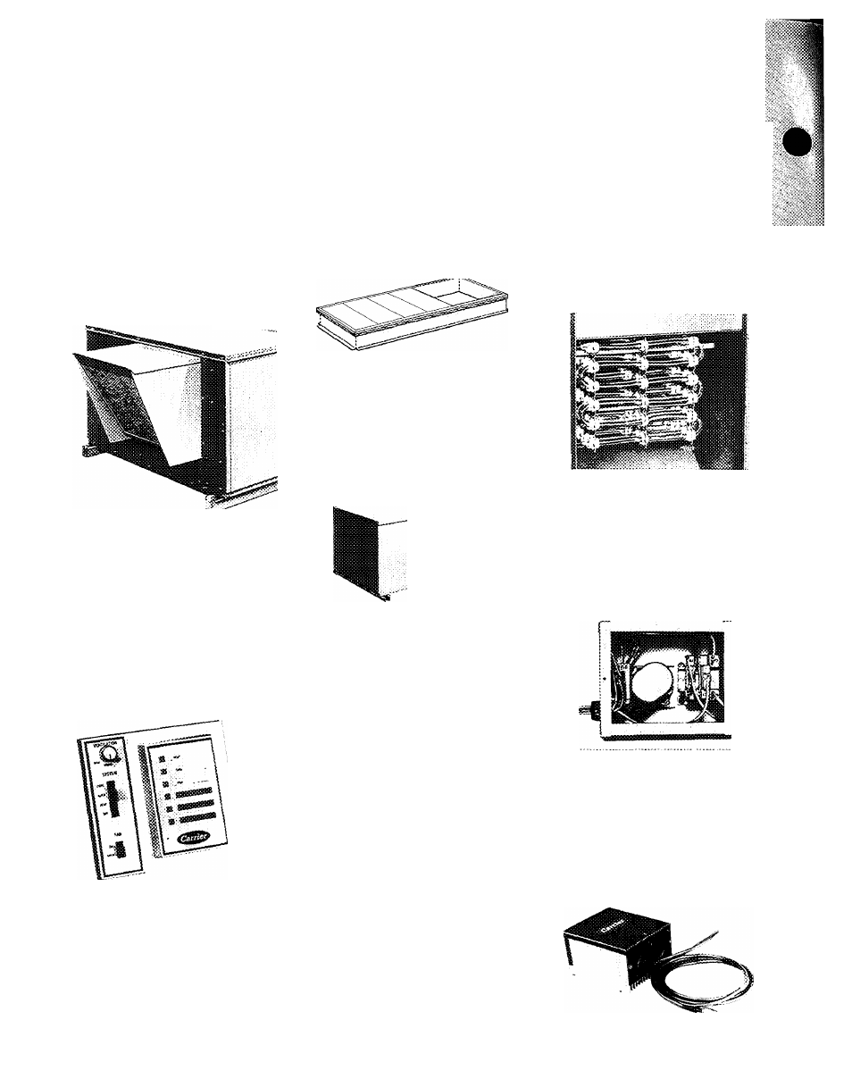
Economizer assembly
is available; as s;
factory-installed option or field-installed;
accessory. Located in plenum, it provides;
low-cost cooling on in-between days,’
Automatically controlled dampers open;
to admit cool, filtered outdoor air The:
compressor(s) and outdoor air fan remain;
off to save energy if the outdoor tern-'
perature is low enough to satisfy cooling;
requirements
without
compressor;
operation.
^
I
Remote control panel
consists of a sep
"marate heating and cooling thermostat'
assembly plus a decorative wall-mounted '
■i-. rj panel In addition to switches for heating,*
:S|cooling and fan operation, the panel
‘i-^^.icontams 6 indicator lights and, for -
■ 4,1 economizer-equipped units, a ventilation.
] control knob.
Roof Curb
with insulated base pans
supports PQ unit (RQ unit with accessory
plenum) and frames roof opening for
plenum and interior ductwork. Once curb
is in place, and ductwork connected, unit
can be placed anytime ~ to meet your
schedule. Curb design meets all National
Roofing Contractors Association (NRCA)
requirements.
Downturn plenum
is standard equipmervL, ■
factory-installed on PQ units, field-;
installed accessory on RQ units. Directs ^
airflow downward and provides weather-;
proof openings for ductwork connec
tions. Unit with plenum is curb mounted.;
^Alternate motor ;tnt( drive,
a factory-
installed cation, provides extra perform
ance
for
instaiiaiioos
requiring
hi^sr
hors^jower
die
standard
motor
has
to offer.
Electric resistance heaters
— Available as
factory-installed option or for field in
stallation Complete with high temper
ature limit switches and overcurrent pro
tection. Qffered in 4 heating capacities
for each unit. Where heaters are factory
I
installed, unit electrical input is single-
;j
point at a factory-supplied terminal
J block. Connection point is suitable for
I copper or aluminum wire (except for
i200-v, 3-phase unit with 1.5 1 electric
:1 heat ratio which uses copper only).
Time Guard® circuit
protects compressore
against thermostat "jiggling," automati-f
cally prevents compressor from restarting-;:
for at least 5 minutes after a shutdown.
Accessory prevents short cycling of com-:-;
pressor if thermostat is rapidly changec;
(field installed)
Thennostat and suUiase (24 V} Acces
sory package provides for selection of
heating, cooling, continuous or automatic
fan cçieratîoR. Works hand-in-fiand with
Signal-LOC circuit. Subbase has v^m-
ing îîÿit (LK-OUT) to automaticaSiy in
dicate
compressor
lockout
condition.
Occupant îs immedîaitely avrare if com
pressor is inoperative Sue to malfunction.
Emergency beat control
— Accessory
emergency heat subbase and relay aliow
occupant to manually switch compressor
off and electric heat on if warning light
indicates system rnaifunction. Can be
used for quick morning warm-up or to
merely lock out compressor.
Outdoor tfoemtostat($)
— Used to lock
out electric heat above certain outdoor
temperature for economical operation.
Fietd-instaiied with wide range of adjust
ments availabie to suit building design
requirements.
i Motormaster® Head Pressure Control —
i Units are designed to operate at outdoor ,
i
temperatures down to 35 F on cooling;
I mode Below 35 F, accessory 32LT ;
I Motormaster control modulates outdoor;
! fan motor to maintain correct condensing >
1 temperature at outdoor temperatures;
down to -20 F.