Typical wiring schematic – Carrier 50PQ User Manual
Page 14
Attention! The text in this document has been recognized automatically. To view the original document, you can use the "Original mode".
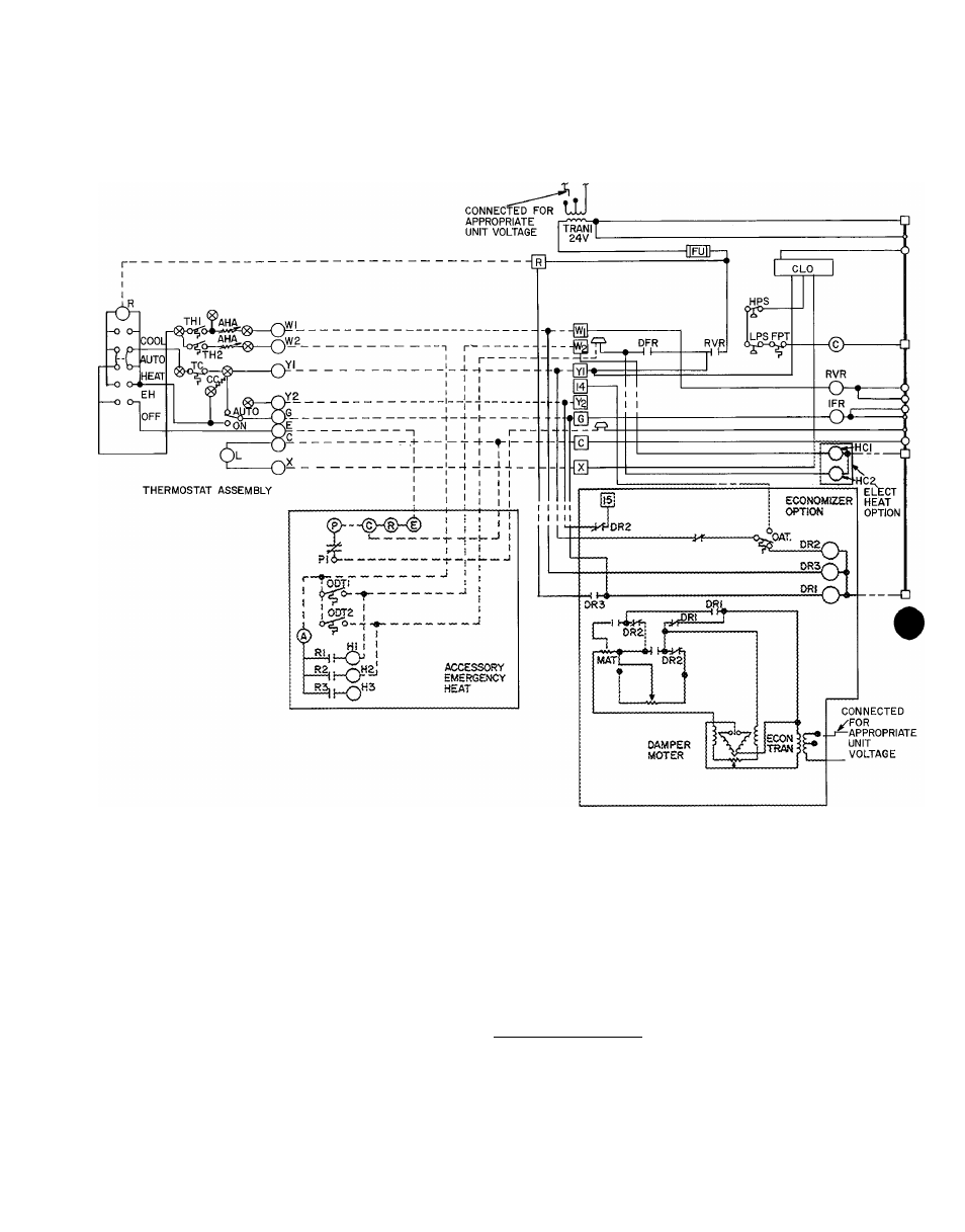
Typical wiring schematic
(Unit 006 shown with electric heat option, economizer option and accessory emergency heat; schematic is for reference only,
do not use for wiring unit.)
UNIT MAIN POWER
#
LEGEND
AHA -
Adjustable Heat Anticipator
TC
Thermostat, Cooling
C
Contactor, Compressor
TH
Thermostat, Heating
CC
Cooling Compensator
TRAN -
Transformer
CLO -
DFR -
Compressor Lock-Out
Defrost Relay
□
Terminal Block Connection
DR -
Damper Relay
o
Terminal (Unmarked)
EH
Emergency Heat
o
Terminal (Marked)
FPT
-
Fu
Freeze-Up Protection Thermostat
Fuse
o
Field Splice
HC -
Heater Contactor
Splice (Marked)
HPS -
High Pressure Switch
__
□
__
Wire Marker
IFR
-
L
Indoor Fan Relay
Lamp
----- •—
Factory Wiring
Factory Splice
LPS -
Low Pressure Switch
______
Accessory or Optional Wiring
MAT. -
Mixed Air Thermostat
______
Field Control Wiring
OAT. -
Outdoor Air Thermostat
M M M
Field Power Wiring
ODT -
Outdoor Thermostat (Emer Heat)
To indicate common potential
RVR -
Reversing Valve Relay
not to represent wire
14