A warning, Electrical controls and wiring, Table 6 — trouble analysis chart – Carrier 58DRC User Manual
Page 8: 58drc counterflow gas-fired furnaces
Attention! The text in this document has been recognized automatically. To view the original document, you can use the "Original mode".
HEATING A COOLING
58DRC
Counterflow Gas-Fired Furnaces
Cleaning Heat Exchanger — If it becomes neces
sary to clean the heat exchanger because of carbon
deposits, soot, etc., proceed as follows’
1. Turn off gas and electrical supply to furnace.
2. Remove front access doors
3. Remove vent pipe enclosure front and flue pipe.
4. Remove draft diverter. Screws are located inside
draft diverter opening.
5. Remove flue baffles from flue outlets of heat
exchanger.
6. Remove secondary air shield and burners. To remove
pilot burner, disconnect pilot supply tube at gas
valve.
7. Clean flue ways with brush and/or vacuum. Check
heat exchanger for leaks and cracks. Replace if
necessary.
8. Replace flue baffles. Be sure all screws are in place
and tight.
9 Replace draft diverter and vent connector. Be sure
screws are replaced and tight.
10. Using vacuum with soft brush attachment, clean
burners, then replace burners and secondary air
shield.
11. Turn on electricity first, then turn on gas. Check for
gas leaks.
A
WARNING
Never use a match or other open flame to check for
gas leaks. Use a soap-and-water solution.
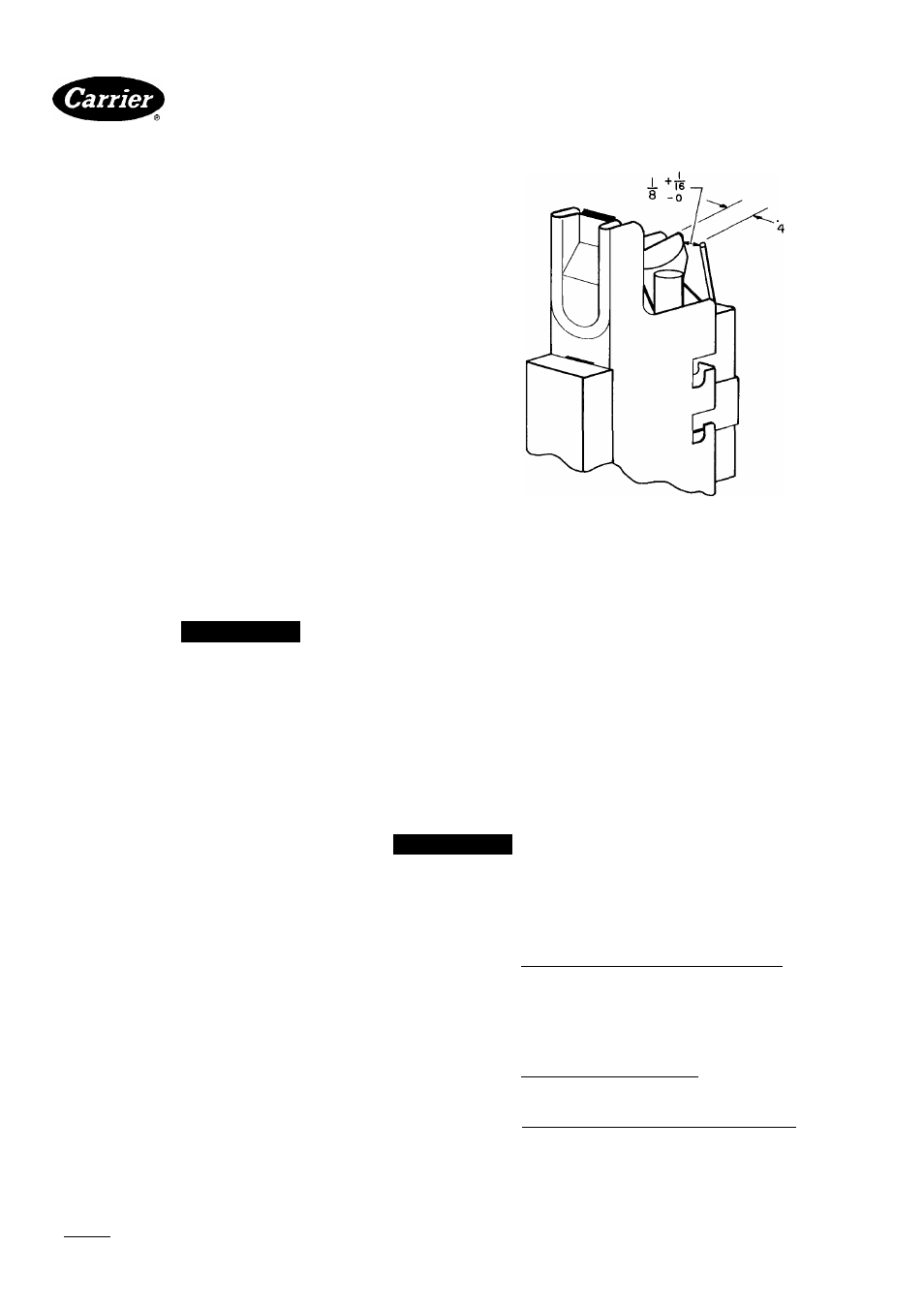
Pilot — See Fig. 15 Check the pilot and clean if neces
sary at the beginning of each heating season. The pilot
flame should be high enough to light the burners. Remove
the accumulation of soot and carbon from the sensing
probe.
I ■*'32
16
Fig. 15 — Position of Electrode to Pilot (in.)
Electrical Controls and Wiring
NOTE: There may be more than one electrical
supply to unit
With power disconnected to unit, check all electrical
connections for tightness. Tighten all screws on electrical
connections If any smoky or burned connections are
noticed, disassemble the connection, clean all parts and
stripped wire, and reassemble properly and securely.
Electrical controls are difficult to check without proper
instrumentation; therefore, reconnect electrical power
to unit and observe unit through one complete operating
cycle. If there are any discrepancies in the operating cycle,
contact your dealer and request service.
Table 6 — Trouble Analysis Chart
A
WARNING
Turn off gas and power supply to unit before servicing
(unless specific test requires gas and electric supplies)
SYMPTOM
CAUSE
REMEDY
Pilot will not light
No spark at electrode
Readjust, if necessary, so that gap between elec-
trode tip and pilot burner is as shown in Fig. 15.
Clean dirt or moisture accumulation from electrode
ceramic with cloth
Cracked
ceramic
assembly
replace pilot electrode
Check for loose or broken wiring at and between
spark generator and electrode Replace wire or
tighten connection as necessary______________________
Check fuse or circuit breaker for 115-volt supply to
furnace.
Check blower access panel for proper installation.
Check 24-volt input to spark generator. If reading is
24 volts, and above steps have been completed,
replace spark generator assembly
Manufacturer reserves the right to discontinue, or change at any time, specifications or designs without notice and without incurring obligations.
BookM |4
PC101
Catalog No 535-843
Printed in U S A
Form 58DRC-1 SI
Pg8
7-85
Replaces:New
For replacement items use Carrier Specified Parts
Tab I6al8a