Electrical connections, A caution, A warning – Carrier 58DRC User Manual
Page 3: 58drc counterflow gas-fired furnaces
Attention! The text in this document has been recognized automatically. To view the original document, you can use the "Original mode".
HEATING & COOLING
58DRC
Counterflow Gas-Fired Furnaces
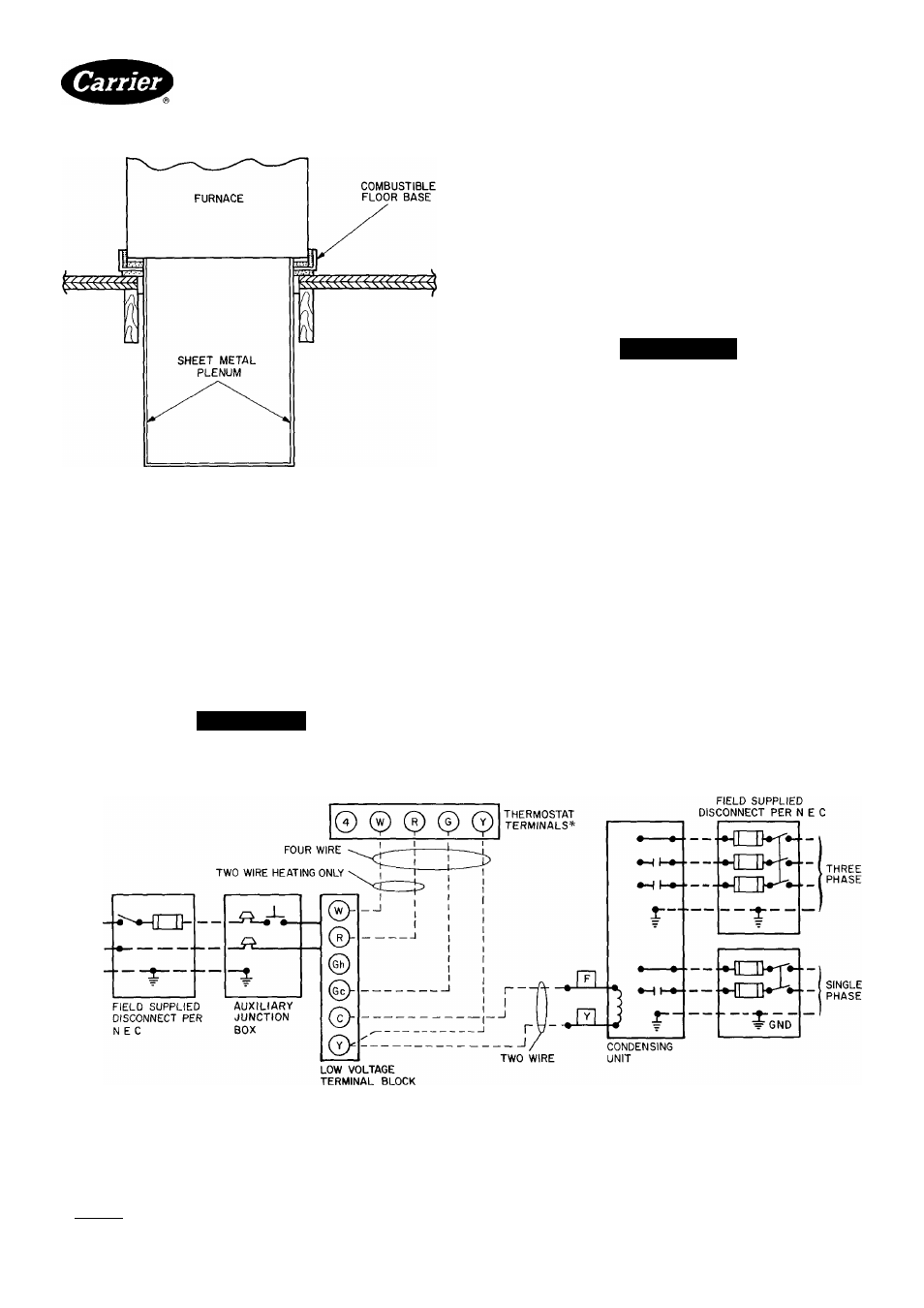
Fig. 6
Furnace, Plenum, and Base Installed
on a Combustible Floor
Electrical Connections
LINE-VOLTAGE WIRING
NOTE. For additional information, refer to Procedures
for Gas-Fired Furnaces (packaged with the equipment)
IMPORTANT: Before proceeding with the electrical
connections, make certain that voltage, frequency,
and phase correspond to that specified on the unit
rating plate. Also, be sure that the service provided
by the utility company is sufficient to handle the addi
tional load imposed by this equipment.
A
CAUTION
Do not connect aluminum wire between disconnect
switch and furnace.
See Fig. 7 for wiring diagram showing the proper field
high- and low-voltage wiring Make all electrical connec
tions in accordance with the National Electrical Code
ANSI/ NFPA 70-1984 and any local codes or ordinances
that might apply.
Use a separate fused branch electrical circuit for this
furnace. A disconnecting means must be located within
sight from, and readily accessible from the furnace. In
some areas, the unit door switch may qualify as the dis
connecting means
A
WARNING
The furnace must be electrically grounded in accord
ance with local codes, the National Electric Code,
ANSI/ NFPA 70-1984 Do not use gas piping as an
electrical ground.
If line voltage wiring to the unit is encased in a non-
metallic sheath, connect the incoming ground wire to the
grounding wire inside the furnace junction box. If
metallic conduit is used, it will serve as the ground.
LOW-VOLTAGE WIRING — Make field low-voltage
connections at the low-voltage terminal strip See
Fig 7.
NOTE: Use AWG no. 18 color-coded copper thermostat
wire for lengths up to 100 feet Above 100 ft, use AWG
no. 16 wire
IMPORTANT The thermostat heat anticipator
must be set to match the amp draw of the gas valve
and electrical components in the R-W circuit.
Accurate amp draw readings can be obtained at
thermostat subbase terminals R and W. Figure 8
illustrates an easy method for obtaining the actual
amp draw.
*Some thermostat subbases require a jumper wire between subbase terminals R and 4 for ---------------------------------------------------
proper operation in heating and cooling applications that use a single transformer
-----------
NOTE If any of the original wire as supplied must be replaced, use same typeor equivalent wire --------------------------------------------
Fig. 7 — Heating and Cooling Application Wiring Diagram
-Field Low-Voltage Wiring
■ Field High-Voltage Wiring
Factory Low-Voltage Wiring
Manufacturer reserves the right to discontinue, or change at any time, specifications or designs without notice and without incurring obligations.
Bookj 1 |4
PC101
Catalog No 535-843
PrintedinUSA
Foi m 58DRC-1SI
Pg 3
7-85
Replaces New