A warning, 58drc counterflow gas-fired furnaces – Carrier 58DRC User Manual
Page 5
Attention! The text in this document has been recognized automatically. To view the original document, you can use the "Original mode".
HEATING & COOLING
58DRC
Counterflow Gas-Fired Furnaces
When the pilot flame is established, pilot 6H switches
its contacts in approximately 40 to 60 seconds, ener
gizing the main valve portion of gas valve 5F and de
energizing pilot igniter 6F and the PICK coil portion of
the pilot solenoid in gas valve 5F.
The main valve portion of gas valve 5F is heat motor
operated; therefore, after approximately 10 seconds, this
portion of the valve opens, permitting gas flow to the
main burners where the gas is ignited by pilot 6H
BLOWER CIRCUIT — With power through the solid-
state time-delay circuit on printed-circuit board 6C1 and
heat relay 2A, blower motor 3D is energized on heating
speed approximately 75 seconds after the pilot flame has
been proven
LIMIT CONTROL — If the furnace overheats for any
reason, limit control 7H1 switches, breaking the circuit
to automatic gas valve 5F The gas valve closes imme
diately, stopping gas flow to the main burners and the
pilot In addition, blower motor 3D continues to operate
because heat relay 2A is de-energized to cool down the
furnace.
Manual reset auxiliary limit switch 7H2 is located on
the top right-hand corner of the furnace. In the event
of blower motor failure, this switch breaks the electrical
circuit to the gas valve, stopping gas flow to the main
burners The switch must be manually reset after the
blower motor has been replaced.
Fusible link IIC is provided in the transformer lA
secondary circuit as protection from overheating con
ditions in the vestibule area of the furnace. Should this
condition exist, the fuse opens and de-energizes gas valve
5F and heat relay 2 A, stopping the gas flow to the burners
and starting blower motor 3D
When the thermostat is satisfied, the circuit between
R and W is broken, de-energizing automatic gas valve
5F, pilot 6H, and the solid-state time-delay circuit on
printed-circuit board 6C1. The gas flow stops imme
diately to the pilot and main burners with the BDP646
gas valve. After approximately 105 seconds, heat relay 2A
is energized and blower motor 3D stops.
MODEL 58GS/SE VENT DAMPER (when used) —
With gas and electrical power supplied to the furnace, the
vent damper is in the closed position. On a call for heat
by the thermostat, the vent damper motor is energized
and the damper opens. When the damper reaches full
open position, the transformer energizes the gas valve.
When the thermostat is satisfied, it de-energizes the
gas valve and stops the gas flow. The vent damper motor
energizes and closes the damper. The damper remains
closed until the next thermostat cycle.
COOLING (cooling models only) — When the thermo
stat calls for cooling, power from transformer lA ener
gizes the condensing unit contactor, cooling relay coil 2F,
closing its contacts and energizing blower motor 3 D on its
cooling speed. It continues to operate until the thermostat
is satisfied.
When the thermostat is satisfied, the circuit to ter
minal Gc is broken, de-energizing cooling relay coil 2F
which, in turn, opens its contacts, stopping blower motor
3D.
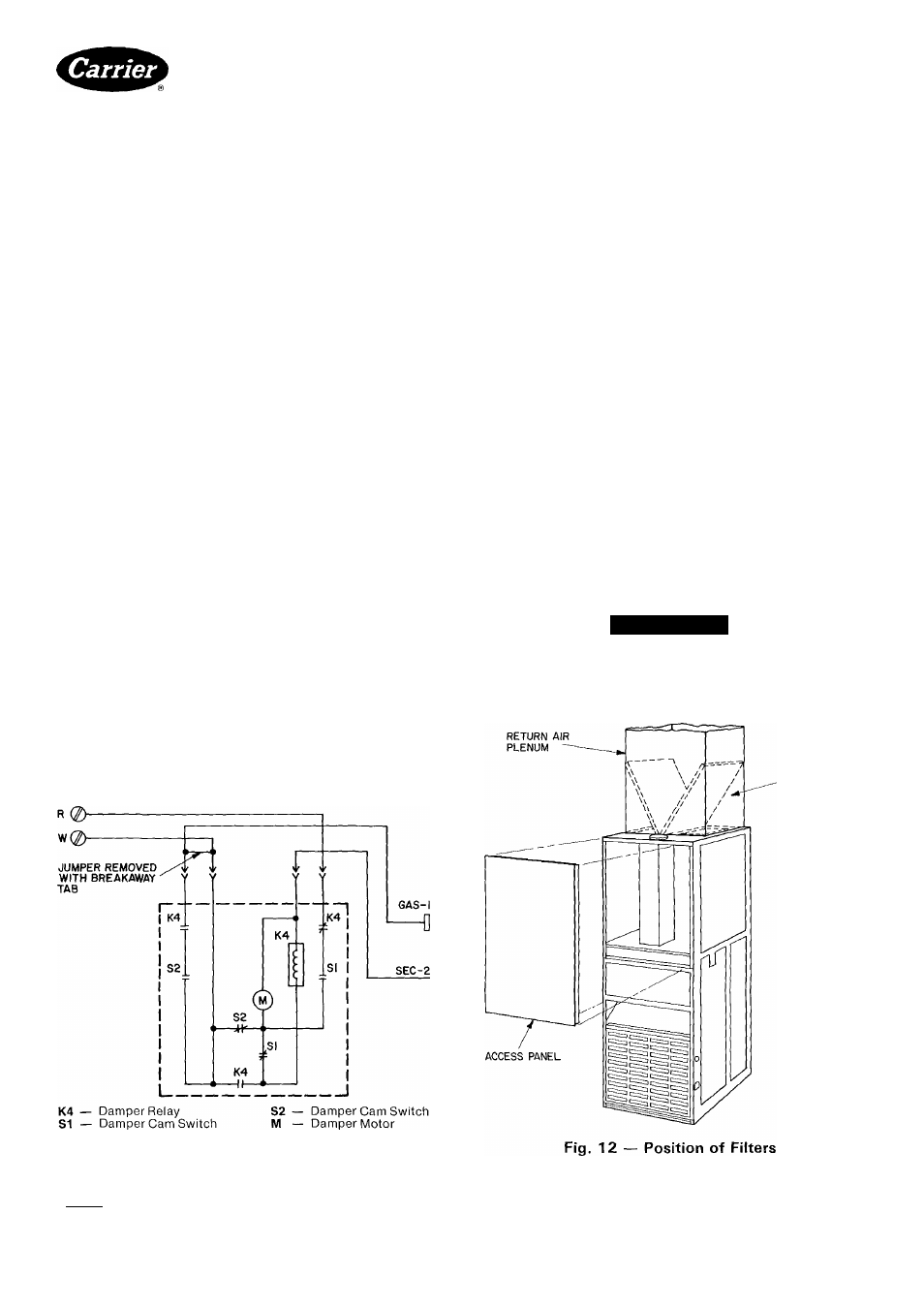
Filter Arrangement — The 2 factory-supplied filters
are shipped in the blower compartment. After the return-
air duct has been connected to the furnace, install the
filters in a V-formation inside the return-air plenum. See
Fig. 12.
A WARNING
Never operate unit without a filter or with filter
access door removed.
Fig. 11 — Circuit for 58GS/SE Vent Damper
INSTALLATION
POSITION
OF FILTERS
Manufacturer reserves the right to discontinue, or change at any time, specilications or designs without notice and without incurring obligations.
Book[1 [4
PC101
Catalog No 535-843
PrintedinUSA
Form58DRC-1SI
Pg5
7-85
Replaces: New
----------------- iromc iiQA Carrier Soecifled Parts