A warning, 58drc counterflow gas-fired furnaces – Carrier 58DRC User Manual
Page 7
Attention! The text in this document has been recognized automatically. To view the original document, you can use the "Original mode".
HEATINC A COOLING
58DRC
Counterflow Gas-Fired Furnaces
The minimum maintenance that should be performed
on this equipment is as follows.
1. Check and clean or replace air filter each month or as
required.
2. Check blower motor and wheel for cleanliness and
lubrication each heating and cooling season. Clean
and lubricate as necessary.
3. Check electrical connections for tightness and controls
for proper operation each heating season. Service as
necessary.
A WARNING
As with any mechanical equipment, personal injury
can result from sharp metal edges, etc.; therefore,
be careful when removing parts.
Air Filter — Each furnace accommodates 2 filters
which are installed above the furnace in the return-air
plenum. See Fig. 12.
To clean or replace the filters, proceed as follows;
1 Disconnect electrical power before removing access
panel.
2. Remove upper access panel.
3. Reach up behind top plate, tilt filters toward center of
return-air plenum, remove filters, and replace or clean
as needed.
4 Some furnaces are equipped with reusable, washable
filters.
a. Clean with tap water.
b. Rinse and let dry. No oiling or coating of filters is
required.
c. Reinstall filters with cross-hatch binding facing
blower.
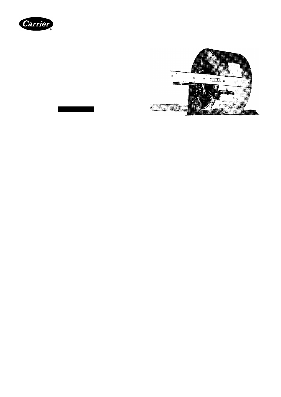
Blower Motor and Wheel (Fig. 14) — Clean and
lubricate as follows;
1. Remove upper access panel.
2. Loosen screw in vent pipe enclosure front and remove
vent enclosure front by sliding forward (toward front
of unit).
3. Disconnect vent pipe at first joint above unit and
swing vent pipe assembly to the side, supported by
suitable means (block of wood, etc.).
4. Slide vent pipe upward through the rectangular open
ing in top plate and remove vent pipe from furnace
5. Remove 4 screws in vent pipe enclosure back and
remove enclosure back by tilting top toward blower,
and sliding bottom toward front of furnace.
6. Disconnect electrical leads from right side of Molex
speed selector. Note location of wires for reassembly.
7. Remove screws holding blower assembly against
blower deck and slide blower assembly out of furnace.
8. Squeeze side tabs of Molex speed selector and pull
it from blower housing.
9. For units with motor capacitor, loosen screw in strap
holding capacitor to blower housing and slide capac
itor from under strap.
Fig, 14 — Dual Blower with Left-Hand Housing
and Wheel Removed
10
.
I I .
12
Mark blower wheel, motor, and motor support in
relation to blower housing before disassembly, to
ensure proper reassembly.
Loosen setscrew holding blower wheel onto motor
shaft.
Remove bolts holding motor mount to blower
housing and slide motor and mount out of housing.
Some motors have a ground wire attached to blower
housing; disconnect it also.
13. Lubricate motor.
a. Remove dust caps or plugs from oil ports located
at each end of motor
b. Use good grade of SAE 20 nondetergent motor oil
and put 16 to 25 drops in each oil port
c. Allow time for total quantity of oil to be absorbed
by each bearing.
d. After oiling motor, be sure to wipe excess oil from
motor housing.
e. Replace dust caps or plugs on oil ports.
14 Remove blower wheel from housing
a. Mark blower wheel orientation and cutoff loca
tion to ensure proper reassembly.
b. Remove screws holding cutoff plate and remove
cutoff plate from housing.
c. Lift blower wheel from housing through opening.
15. Clean blower wheel and motor by using vacuum with
soft brush attachment. Care must be exercised not
to disturb balance weights (clips) on blower wheel
vanes. Also do not drop or bend wheel, as balance
will be affected.
16. Reassemble blower by reversing procedures 14a-14c.
Be sure wheel is positioned for proper rotation.
17 Reassemble motor and blower by reversing pro
cedures 8-12. If motor has ground wire, be sure it is
connected as before.
18. Reinstall blower assembly in furnace.
19. Reinstall vent enclosure back.
20. Reinstall vent pipe through opening in top plate,
secure to draft hood and connect remainder of vent
pipe assembly.
21 Reinstall vent enclosure front, and secure with screw.
22. Reinstall access panel
Manufacturer reserves the right to discontinue, or change at any time, specifications or designs without notice and without incurring obligations
Bookll ¡4
PC 101
CatalogNo 535-843
PrintedinUSA
Form58DRC-1SI
Pg7
7-85
Replaces;New
For replacement items use Carrier Specified Parts
Tah I6al8a