Sequence of operation, 58drc counterflow gas-fired furnaces – Carrier 58DRC User Manual
Page 4
Attention! The text in this document has been recognized automatically. To view the original document, you can use the "Original mode".
HEATING A COOUHG
58DRC
Counterflow Gas-Fired Furnaces
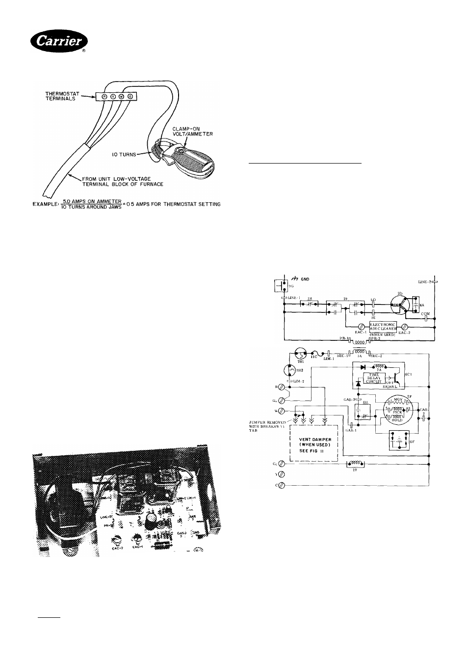
Fig. 8 — Amp Draw Check with Ammeter
The room thermostat should be located where it will
be in the natural circulation path of room air. Avoid loca
tions where the thermostat would be exposed to cold-air
infiltration, drafts from windows, doors, or other open
ings leading to the outside, or exposure to air currents
from warm- or cold-air registers; or to exposure where
the natural circulation of the air iS- cut off — such as
behind doors, above or below mantels, shelves, etc
The thermostat should not be exposed to heat from
nearby fireplaces, radios, televisions, lamps, or rays from
the sun. Nor should the thermostat be mounted on a wall
containing pipes or warm-air ducts, or a flue or vent that
could affect its operation and prevent it from properly
controlling the room temperature. Any hole in the plaster
or panel through which the wires pass from the thermo
stat should be adequately sealed with suitable material to
prevent drafts from affecting the thermostat
PRlNTED-ClRCUlT CONTROL CENTER — Each
furnace features a printed-circuit control center. This will
aid the installer and service technician when installing and
servicing the unit. See Fig. 9. A low-voltage terminal
board is marked for easy connection of field wiring.
4 и
^ Н
Fig. 9 — Printed-Circuit Control Center
Sequence of Operation
NOTE; The wiring diagram shown in Fig. 10 is for
heating/cooling units.
HEATING — Gas and electrical supplies must be turned
on at the furnace.
NOTE; When power is applied to heat relay coil 2 A in the
control circuit, the normally closed contacts in the blower
circuit will open.
BDP 646 Gas Valve (HD Models) — When the thermo
stat calls for heat, the control circuit is closed between
terminals R and W. Power from transformer 1A through
fusible link 11C and limit switches 7H1 / 7H2 energizes the
pilot valve portion of automatic gas valve 5F and pilot
igniter 6F. The pilot valve opens, permitting gas flow to
the pilot burner where it is ignited.
The pilot valve portion of automatic gas valve 5F is a
solenoid consisting of a PICK and a HOLD coil. Both
the PICK and the HOLD coils must be energized to open
the valve, but only the HOLD coil must be energized to
keep it open
1A
2A
2F
3D
4A
5F
6C1
6F
6H
Transformer 115/24
Relay-Heat (SPST-
N C )
Relay-Cool (DPDT)
Blower Motor
Run Capacitor
Gas Valve (2-Circuit)
Printed-Circuit Board
Piiot Igniter
Safety Pilot (Flame
Sensing)
7H1
— Limit Switch (SPST-
N C )
7H2
— Auxiliary Limit Switch
(SPST-N C ) Manual
Reset
Summer/Winter
Switch (if equipped)
Blower Door Switch
(SPST-N O )
Fusible Link
9A
9G —
11C
Fig. 10 — Line-to-Line Wiring Diagram for
Sizes 045-095 IID Natural Gas
Manufacturer reserves the right to discontinue, or change at any time, specifications or designs without notice and without incurring obligations
Book|1 14
PC101
Catalog No 535-843
Printed in U S A
Form 58DRC-1 SI
Pg4
7-85
Replaces:New
ronlanorvionf Home iica
Cna^iticw4 Dat-fc