Winco ULPSS21/E WITH DSE 7310 ENGINE CONTROL User Manual
Page 7
60706-240
Page 5
3025-00
LP LIQUID WITHDRAWAL SYSTEMS
When installing a unit equipped the LP liquid withdrawal a primary
regulator is not required on the supply tank. The supply line is
connected to a liquid withdrawal valve on the supply tank and runs
directly to the fuellock strainer mounted on the engine generator
set. Normally a 3/8 to 1/2 inch copper line is acceptable for this
type of fuel installation. You must be sure that the valve you have
connected to on the supply tank is in fact a liquid supply valve and
has a drop tube inside the tank that is pulling fuel from the bottom
of the supply tank. Before starting the unit you must confirm that
you have a good liquid supply at the unit.
Engine generator sets
equipped for liquid withdrawal will not run properly when
supplied with high pressure vapor fuel.
LUBRICATION
Before starting the engine, check the oil level in the crankcase.
If it is low, refill to the full mark with the proper weight/grade of
oil as recommended by the engine manufacturer’s maintenance
instructions. The necessity of using the correct oil, and keeping
the crankcase full cannot be over emphasized. Failure to use the
proper oil and keep the crankcase properly filled will cause exces-
sive engine wear and shorten its useful life.
COOLANT
Before starting the engine, check the coolant level in radiator. If it
is low, refill as specified in the engine manufacturer’s maintenance
instructions. The radiator should be filled to about 1 inch below
the filler neck. For additional information on engine coolant re-
quirements see engine manufacturer’s maintenance instructions.
INSTALLING THE BATTERY
**** CAUTION ****
In the following battery installation procedure, check to be sure the
selector switch remains in the “stop” position. This should be your
last step before initial start-up.
A customer supplied twelve-volt battery is required to complete
the installation. Installation of the highest CCA rated battery,
within the correct BCI group, will increase cold weather starting
performance. Gel batteries should not be used with the battery
tender installed in the generator enclosure.
MINIMUM
Model
Voltage
BCI Group CCA Rating
PSS21 12 24
650
Installation and servicing of batteries must be performed or
supervised only by personnel knowledgeable of batteries and the
required precautions. Keep unauthorized personnel away from
batteries
.
When installing or replacing batteries, use the proper group/size
starting battery. The battery should be a Maintenance Free lead
acid design. Deep cycle batteries will not work for this applica-
tion.
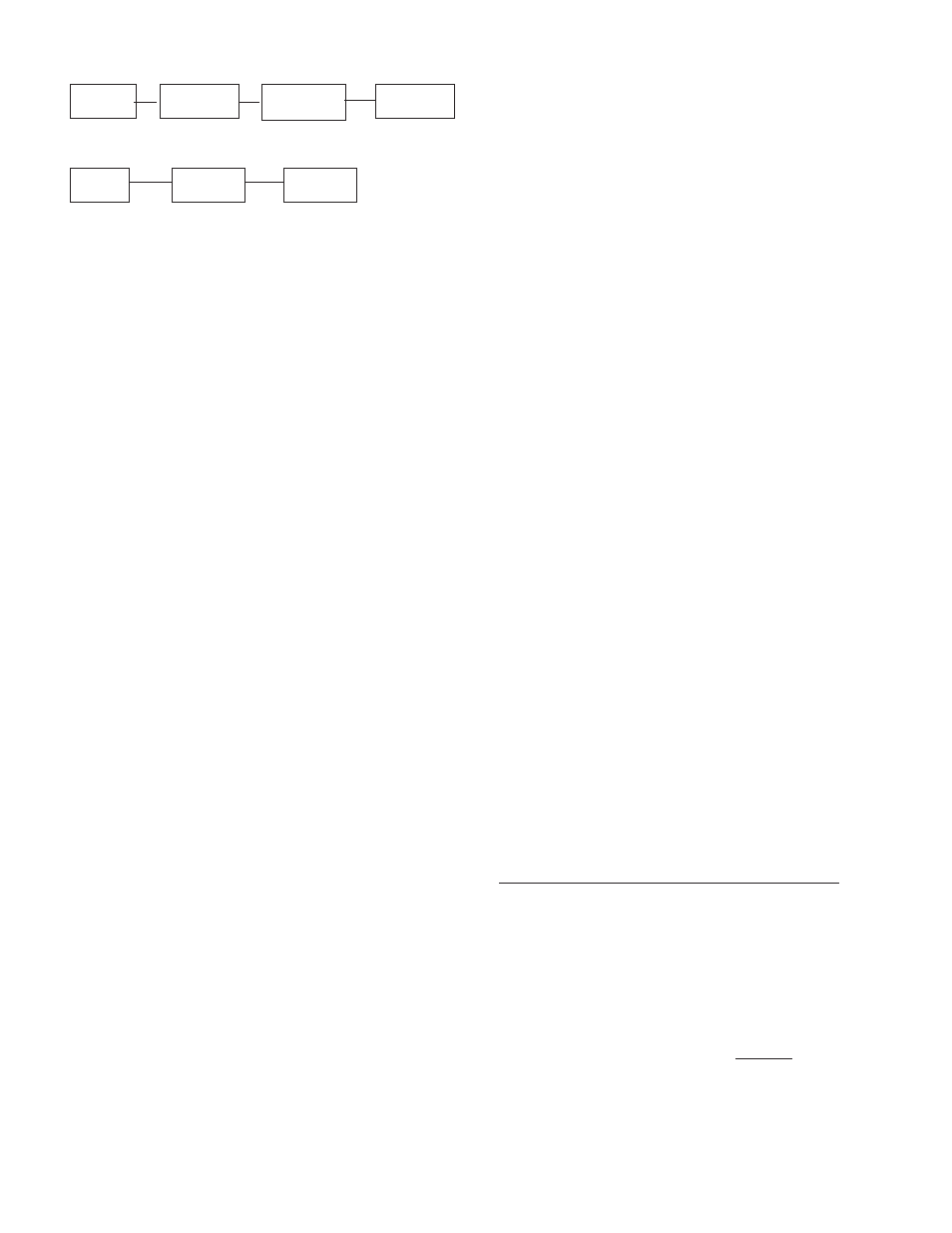
Supply Primary
Secondary
Generator
Tank
Regulator
Regulator
Set
1 2
3
4
TWO (2) REGULATOR FUEL SYSTEM
Supply
Primary
Generator
Tank
Regulator
Set
1 2 4
SINGLE REGULATOR FUEL SYSTEM
Reference numbers 1 through 3 in the block diagrams above are
fuel lines supplied by customer.
Reference number 4 is the engine generator set.
Below is a table of the fuel pressure readings at each reference in
the system.
Fuel Pressure Table
Single Regulator (L.P. Vapor only)
1
2 3
UNIT OFF
TANK PSI
7-11 in 7-11 in
4-6 oz. 4-6 oz.
STARTING
TANK PSI
7-11 in 7-11 in
4-6 oz. 4-6 oz.
NO LOAD
TANK PSI
7-11 in 7-11 in
4-6 oz. 4-6 oz.
FULL LOAD
TANK PSI
7-11 in 7-11 in
4-6 oz. 4-6 oz.
Two (2) Regulator System (L.P. Vapor only)
1
2
3
4
UNIT OFF
TANK PSI 10-15 lbs 7-11 in
7-11 in
4-6 oz. 4-6 oz.
STARTING TANK PSI 10-15 lbs 7-11 in
7-11 in
4-6 oz.
4-6 oz.
NO LOAD
TANK PSI 10-15 lbs 7-11 in
7-11 in
4-6 oz. 4-6 oz.
FULL LOAD TANK PSI 10-15 lbs 7-11 in
7-11 in
4-6 oz. 4-6 oz.
Natural Gas
1
2
4
UNIT OFF
LINE PSI
7-11 in
7-11 in
4-6 oz.
4-6 oz.
STARTING
LINE PSI
7-11 in
7-11 in
4-6 oz.
4-6 oz.
NO LOAD
LINE PSI
7-11 in 7-11 in
4-6 oz.
4-6 oz.
FULL LOAD
LINE PSI
7-11 in.
7-11 in
4-6 oz.
4-6 oz.
Notice the preceding tables give two (2) different units of measur-
ing fuel pressure. The first is with a pressure gauge calibrated in
ounces per square inch. The second and most accurate is the
use of a simple water manometer. A manometer is calibrated in
inches of water column.