Engine control panel layout, Controller, Table a. generator start connections – Winco ULPSS21/E WITH DSE 7310 ENGINE CONTROL User Manual
Page 11: 4 --- settings, 5 --- automatic generator exerciser, Clock battery, Exercise with or without load, Table b. generator exercise settings
60706-240
Page 9
3025-00
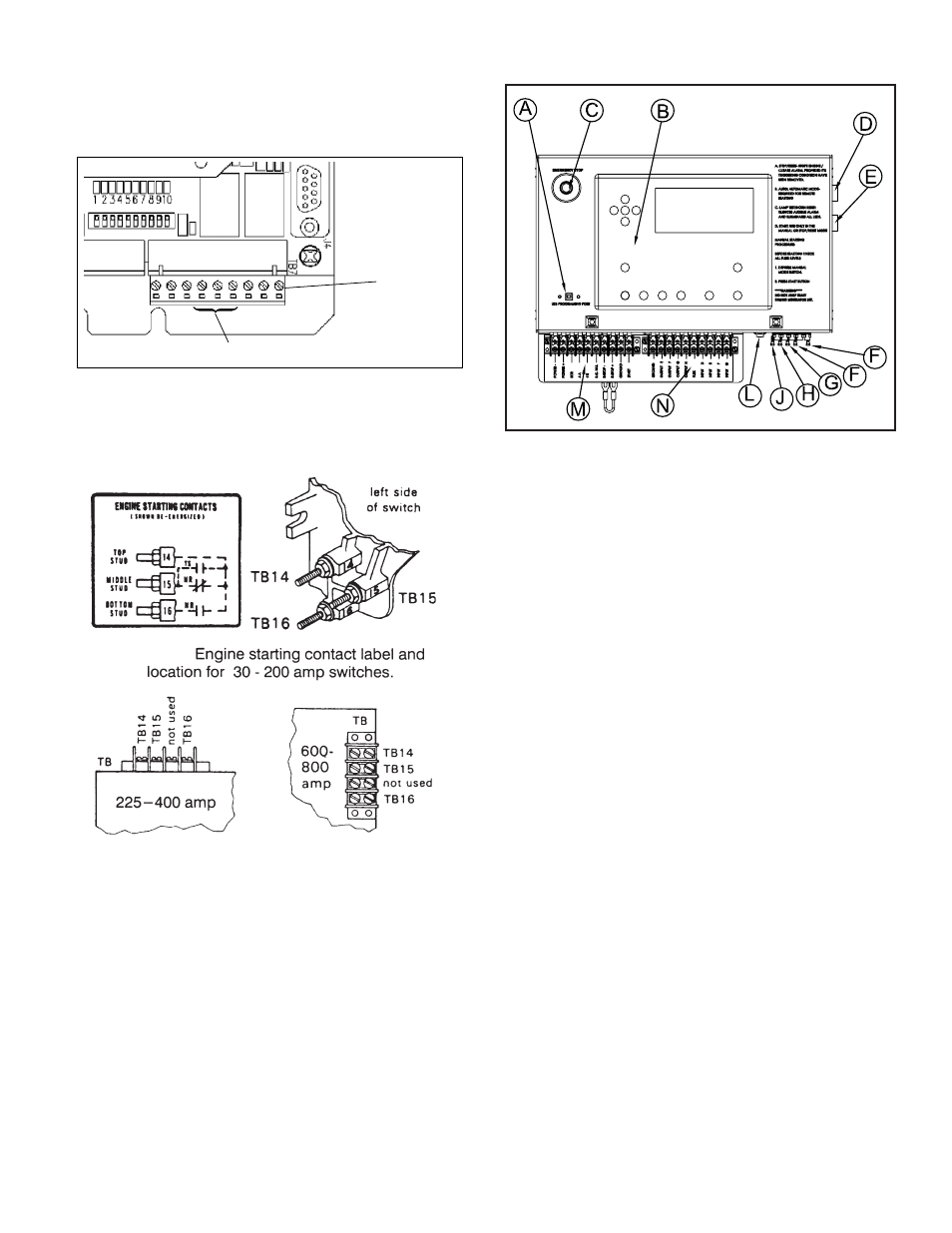
ASCO 185 UL SWITCH
Your DC connection points in the ASCO 185 ATS are
terminals “4” and “5 on the interface terminal block.
ASCO 300 UL SWITCH
Your DC connection points in the ASCO 300 ATS are terminals
“14” and “15”. Depending on the size of the switch they are lo-
cated in different locations.
ENGINE CONTROL PANEL
LAYOUT
A. USB PROGRAMMING PORT - USB port for computer inter-
face. Used for programming the DSE7310 controller.
B. DSE7310 CONTROLLER - See controller explanation on fol-
lowing page.
C. Emergency Stop Switch - When depressed this switch will
disconnect all the 12 volt power to the DSE7310 shutting the
engine down. The display on the controller will annunciate “Emer-
gency Stop”.
D. AC INTERFACE CONNECTOR - This connector is used to
interface with the AC generator end. It provides the controller with
the voltage, amperage and frequency reading for the display.
E. DC INTERFACE CONNECTOR - This connector provides all
the interface connections for the engine, including the DC power
supply to operate the DSE7310 controller. Engine CAN connec-
tions are also made through this connector providing the controller
with the engine operational reading.
F. 10 AMP FUSE - This fuse supplies the DSE7310 controller 12
Volt DC for all controller functions. (Replacement ATO-ATC 10A-
250V)
G. 3 AMP FUSE -This fuse is in the power supply for the
DSE7310 controller circuitry on the board. (Replacement ATO-
ATC 3A-250V)
H, J, K. 2 AMP FUSE- These fuses are in the AC input line from
the generator. These are the feeds that provide the AC voltage
reading on the display. If one of these is blown the controller will
not show the proper voltage on one leg and may shutdown for low
voltage. (Replacement ATO-ATC 2A-250V)
L. FUEL SELECTOR SWITCH - This switch changes the engine
operating fuel from NG (lwith the switch open ) to LP (with the
switch closed) This selector switch tells the engine ECU what fuel
you are supplying. The engine ECU then makes the appropri-
ate changes in the engine electronics to handle the fuel of your
choice.
M. CUSTOMER REMOTE CONNECTIONS - See detail on previ-
ous page.
N. CUSTOMER EXPANDED INTERFACE CONNECTIONS - Not
used in standard product.
CONTROLLER
Series 185
(continued)
3
381333–319 D
3 --- Generator Starting Contacts
The generator starting contacts connections are on the
controller. Refer to the generator manual. Disconnect
the generator battery and verify that the ignition switch is
in the OFF position. Connect the generator starting
wires to the appropriate terminals on terminal block TB7
as shown on the wiring diagram. For wiring convenience
terminal block TB7 has a removable plug. See Figure 4
and Table A.
TB7
removable
terminal block
TB7–4, TB7–5, TB7–6
1 2 3 4 5 6 7 8 9
Figure 4. TB7 generator starting contact terminals.
Table A. Generator Start Connections
When the Utility fails
Terminals on Controller
contact closes
TB7–4 and TB7–5
contact opens
TB7–5 and TB7–6
4 --- Settings
The time delay and sensor setting in the Group 4
controller are accessible on the inside. Refer to Tables B
and C and to Figures 6 and 7. Use a ball–point pen or
other pointed tool to slide the DIP switch actuators up or
down to match setting shown.
All power must be off before making any changes.
The factory default settings are shown in Table G on
page 5.
screw
cover must be removed
to replace 9V battery
(use alkaline type)
Figure 5. Battery replacement.
5 --- Automatic Generator Exerciser
The built–in automatic generator exerciser can be set to
exercise the generator for 20 minutes once every week.
Clock Battery
Be sure a fresh battery is installed and turned on. It will
maintain the exerciser clock for about 24 hours in case of
a power outage.
Recommended 9 volt alkaline batteries are (see Figure
5): Duracell MN 1404, Everready 522, Panasonic 6AM6
Turn on battery by putting S2 DIP switch actuator 10 in
the on position (up). See Table B and Figure 6.
Exercise with or without Load
The generator should be exercised under load or follow
the recommendations of the generator manufacturer. Be
sure the exerciser is turned on. Then select either
exercise with or without load. The ATS will transfer the
load to the generator when the exercise with load is
selected. See Figure 6 and Table B.
Table B. Generator Exercise Settings
Function
Factory
Setting
DIP
Switch
DIP
Actuator
Actuator
Position
clock
battery
off
S2
10
on (up)
off (down)
exerciser
off
S1
7
on (up)
off (down)
with load or
without load
without
load
S1
8
with (up)
without (down)
To Set Exerciser
Press and hold (5 seconds) the Set Engine Exerciser
button. The exercise period occurs immediately and at
approximately the same time weekly thereafter. The
status light below the button blinks during the exercise
period (including the cooldown). The light stays on to
indicate that the exerciser has been set. If the light is off,
the exerciser has not been set.
To Cancel an Active Exercise Period
Press the Bypass Time Delay button to stop an exercising
generator. If exercise with load is set, the ATS
retransfers the load to the utility, then stops the
generator after cooldown.