D.c. electrical connections – Winco ULPSS21/E WITH DSE 7310 ENGINE CONTROL User Manual
Page 10
Page 8
3025-00
60706-240
Depending on the distance, 14 to 16 gauge stranded wire should
be used. It is suggested that these wires be labeled S1 and S23.
The terminal blocks are designed to use terminal lugs on all wires
and the screws should be torqued to 9.6 in. lbs.
Note: Any relay closure can be used to start and stop this
generator. As long as the contact stays closed the engine
generator set will continue to run. Once the relay is opened
the unit will shut down and remain in the standby mode until
the remote start relay is closed again.
B - ESTOP- & ESTOP+. Remote Emergency Stop terminals.
These two terminals are shipped with a jumper installed. If your
application requires the installation of a Remote Emergency Stop
switch, remove the jumper and wire your switch to these termi-
nals.
This unit will not start and run without either the jumper
installed or a remote N/C switch installed.
C - Battery Charger Failure. Battery charger failure relay input
from remote battery charger to DSE7310 controller.
D - Remote Display Panel Interface Terminals. These interface
terminals are prewired to allow for the connection of a remote
display. This display allows for the remote annunciation of alarms
at a location such as a nurses station or a control room.
****************
***** WARNING *****
****************
Be sure Engine Generator is in the "OFF" position before you
make any DC interconnections.
**** CAUTION ****
Never run the AC and DC wiring in the same conduit.
NOTE: The right hand half of the customer connection
terminal block is for programmable inputs and outputs.
Although these terminals are wire into the DSE7310,
they are normally not programed. This terminal block
has connections for four programmable input and four
outputs along with one flex input and a ground. Con-
sult the Factory at 507-357-6831 before attempting to
program these inputs/outputs.
See the manual shipped with the Automatic Transfer Switch for
connection locations in the switch. Connections in each switch
will vary depending on the type of switch and the manufacturer.
GROUNDING
A grounding lug has been provided on the engine generator set to
ground to earth ground if required. Check with your local codes.
Generally a 6 foot copper rod driven into the earth will provide a
proper earth ground.
D.C. ELECTRICAL
CONNECTIONS
NOTE:
There are various DC connectors on the engine that have
nothing connected to them. This was done intentionally,
these connectors are for END OF LINE TESTING and other
various diagnostic tests. They are not used during normal
operations and can just be ignored.
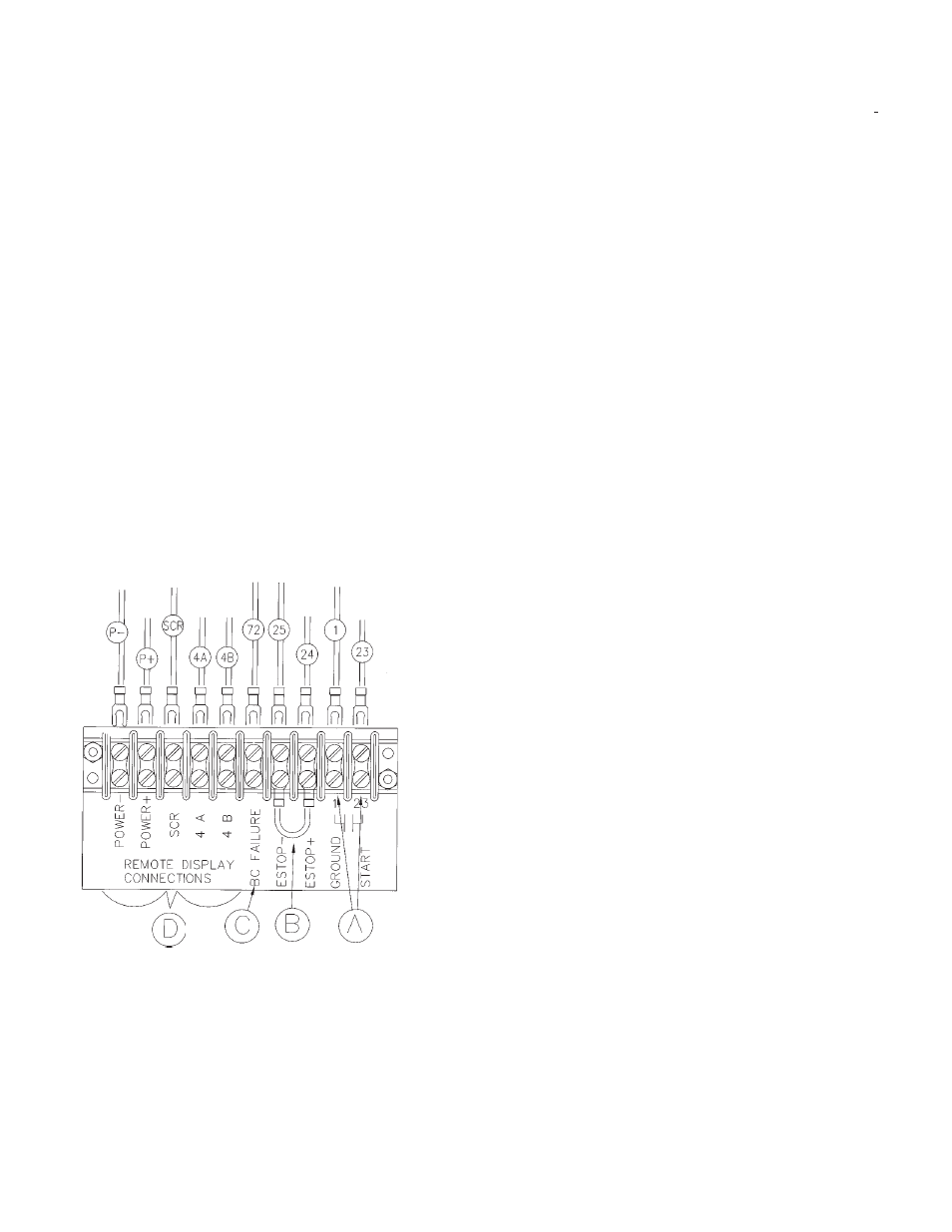
All normal DC connections are completed on the left hand termi-
nal strip just below the engine control cabinet. See Below.
A - Customer Remote Start CONNECTIONS TERMINALS. The
two remote start leads from the Automatic Transfer Switch are
connected to the two terminals marked 1 & 23. The wire in ter-
minal labeled #1 is Battery Negative and the wire in the terminal
labeled #23 is your Remote Start lead. Closing these two leads
together will signal the DSE 7310 to go into an auto-start mode
and start up the engine generator.
Page 8
2090-00
60706-227
Depending on the distance, 14 to 16 gauge stranded wire should
be used. It is suggested that these wires be labeled S1 and S23.
The terminal blocks are designed to use terminal lugs on all
wires and the screws should be torqued to 9.6 in. lbs.
Note: Any relay closure can be used to start and stop this
generator. As long as the contact stays closed the engine
generator set will continue to run. Once the relay is opened
the unit will shut down and remain in the standby mode until
the remote start relay is closed again.
B - ESTOP- & ESTOP+. Remote Emergency Stop terminals.
These two terminals are shipped with a jumper installed. If your
application requires the installation of a Remote Emergency Stop
switch, remove the jumper and wire your switch to these termi-
nals.
This unit will not start and run without either the jumper
installed or a remote N/C switch installed..
C - Battery Charger Failure. Battery charger failure relay input
from remote battery charger to DSE7310 controller.
D - Remote Display Panel Interface Terminals. These interface
terminals are prewired to allow for the connection of a remote
display. This display allows for the remote annunciation of alarms
at a location such as a nurses station or a control room.
****************
***** WARNING *****
****************
Be sure Engine Generator is in the "OFF" position before you
make any DC interconnections.
**** CAUTION ****
Never run the AC and DC wiring in the same conduit.
Zenith ATS
The terminal markings in the Zenith ATS are marked “X1” and
“X2”. The wire labeled “Start 1” is routed to start contact "X1” and
the wire labeled “Start 23” is routed to start contact “X2”
See the manual shipped with the Automatic Transfer Switch for
connection locations in the switch. Connections in each switch
will vary depending on the type of switch and the manufacturer.
GROUNDING
A grounding lug has been provided on the engine generator set
to grounded to earth ground if required. Check with your local
codes. Generally a 6 foot copper rod driven into the earth will
provide a proper earth ground.
D.C. ELECTRICAL
CONNECTIONS
NOTE:
There are various DC connectors on the engine that have
nothing connected to them. This was done intentionally,
these connectors are for END OF LINE TESTING and other
various diagnostic tests. They are not used during normal
operations and can just be ignored.
All DC connections are completed on the terminal strip just below
the engine control cabinet.
A - Customer Remote Start CONNECTIONS TERMINALS. The
two remote start leads from the Automatic Transfer Switch are
connected to the two terminals marked 1 & 23. The wire in
terminal labeled #1 is Battery Negative and the wire in the
terminal labeled #23 is your Remote Start lead. Closing these two
leads together will signal the DSE 7310 to go into an auto-start
mode and start up the engine generator.
X1
X2